pg. 11
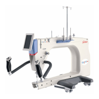
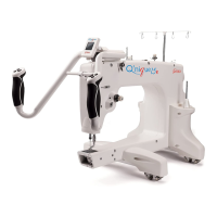
Fig.8
Sewing Machine
Channel Lock
M6 x 20mm SBHCS
Carriage
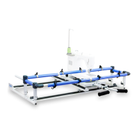
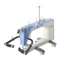
Fig.9b
Top Plate Optional
Accessory
Carriage
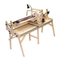
Fig.9a
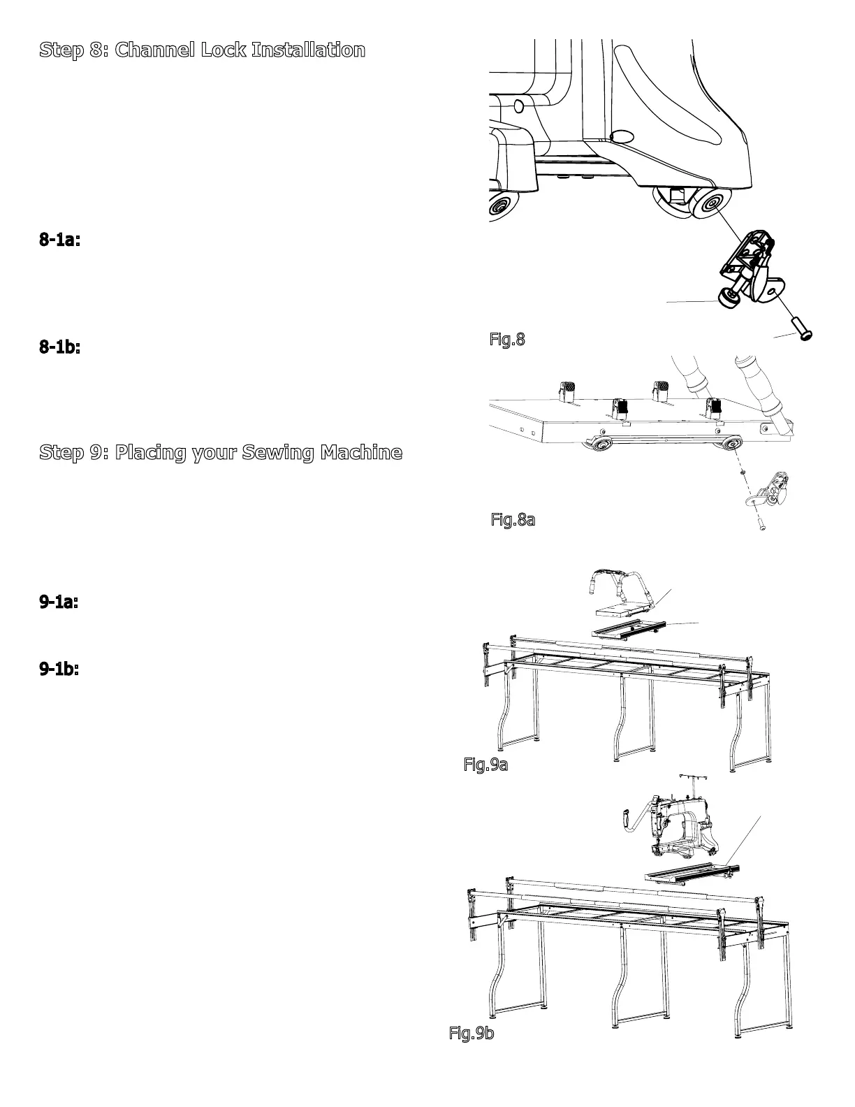
Step 8: Channel Lock Installation
Parts Needed:
-Top Plate Assembly (1) Optional
Accessory
-Frame body Assembly (1)
-Sewing Machine Channel Lock with Spacer (1)
- Carriage Channel Lock (1)
8-1a: Remove the right rear M6 x 16mm SBHCS
from the Sewing Machine and install the Sewing
Machine Channel Lock using the M6 x 20mm SBHCS
as shown, see Fig.8.
8-1b: Remove the right rear M6 x 20mm SBHCS
from the Top Plate Optional Accessory and install
the Top Plate Channel Lock using the M6 x 20mm
SBHCS as shown, see Fig.8a
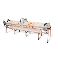
Step 9: Placing your Sewing Machine
Parts Needed:
-Cam Clamp (4)
-Assembled Carriage and Frame (1)
9-1a: Place optional Top Plate Assembly
onto the frame as shown, see Fig9a.
9-1b: Place the Carriage and Sewing Machine
onto the frame as shown, see Fig9b.
Fig.8a
M6 x 20mm SBHCS
Top Plate Channel Lock
Channel Lock Washer