Service
308647T 13
Service
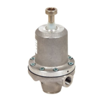
Service Kits
For the Fluid Diaphragm Repair Kit, order Part 238747.
Parts included in this kit are marked with an asterisk, for
example (7*), in Parts, starting on page 16.
For the Cartridge Repair Kit, order Part 238748 for all
models except 248090. Parts included in this kit are
marked with a dagger, for example (3t), in Parts,
starting on page 16.
For the Cartridge Repair Kit for 248090, order Part
248098. Parts included in this kit are marked with a
checkmark, for example (3v), in Parts, starting on page
16.
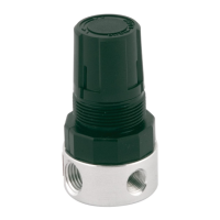
To convert from a spring-operated to an air-operated
regulator, order the Air-Operated Conversion Kit, Part
238749. Parts included in this kit are marked with a
double dagger, for example (37+), in Parts, starting on
page 16.
NOTE: To convert from a medium-pressure-range,
spring-operated model to a high-pressure-range,
spring-operated model (or vice versa), order the
appropriate spring (11) from the parts lists in Parts,
starting on page 16.
Prepare Equipment for Service
1. Follow the Pressure Relief Procedure, page 10.
2. Follow the Flushing Procedure, page 11.
Install the Air-Operated
Conversion Kit
(See Parts Drawings on pages 14-17)
1. Prepare Equipment for Service. Follow steps on
page 13.
2. On the spring-operated regulator, turn the adjusting
screw (10) counterclockwise until it is loose enough
to fully relieve the spring tension.
3. Use a strap wrench or an equivalent wrench to
loosen and remove the spring cover (2), spring
retainers (6 and 27), and spring (11).
4. Place the stabilizing spring (22) of the air-operated
regulator on the piston rod (6). Install the
conversion kit assembly onto the backing plate (8).
Torque to 15 to 20 ft-lb (20 to 27 N•m).
5. Plumb an air line up to the 1/4 npt(m) threads of the
nipple (35) on the air regulator.
6. Flush the system (see page 10), and set the
regulator pressure by following the procedure in
Adjusting the System Pressure on page 9.
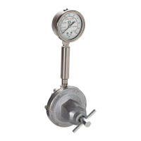
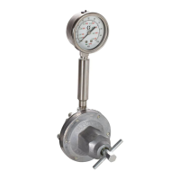
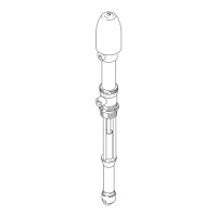
Replacing the Fluid Diaphragms
See Fig. 3, and follow the steps below. For parts that
are not called out in Fig. 3, see Parts, starting on page
16.
1. Prepare Equipment for Service. Follow steps on
page 13.
2. Turn the adjusting screw (10) counterclockwise until
it is loose to fully relieve the spring tension.
3. Remove the four base housing screws (9) from the
base housing (4), and pull the base housing free of
the backing plate (8).
4. Remove the diaphragm and valve actuator
subassembly (1, 7, 12, 13, and 19).
5. Clean and inspect the bore in the backing plate (8)
fo
r wear, and replace it if necessary.
This equipment stays pressurized until pressure is
manually relieved. To help prevent serious injury from
pressurized fluid, such as skin injection and
splashing fluid, follow the Pressure Relief
Procedure, page 10, before servicing the equipment.