psi
bar
MPa
17309674
Pressure Control Repair
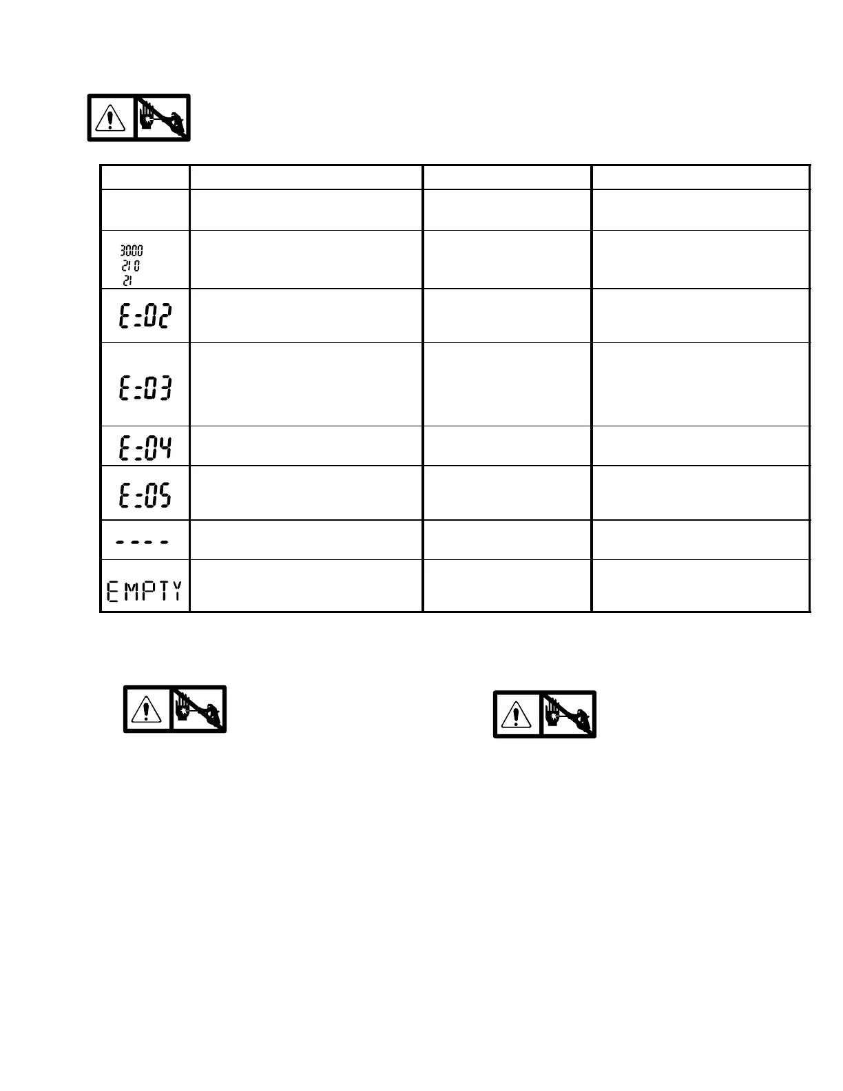
Digital Display Messages
No display does not mean that sprayer is not pressurized. Relieve pressure before repair; page 4.
DISPLAY
SPRAYER OPERATION
INDICATION ACTION
No Display
Sprayer stops. Power is not ap-
plied. Sprayer may be pressurized.
Loss of power Check power source. Relieve pres-
sure before repair or disassembly.
Sprayer is pressurized. Power is
applied. (Pressure varies with tip
size and pressure control setting.)
Normal operation Spray
Sprayer may continue to run. Power
is applied.
Pressure greater than 4500
psi (310 bar, 31 MPa) or
pressure transducer faulty
Replace pressure control board or
pressure transducer.
Sprayer stops. Power is applied.
Pressure transducer faulty,
bad connection or broken
wire.
Check transducer connection.
Open drain valve. Substitute new
transducer for transducer in spray-
er. If sprayer runs, replace trans-
ducer.
Sprayer stops. Power is applied.
Line voltage too high Check for voltage supply problem
Sprayer does not start or stops.
Power is applied.
Motor fault Check for locked rotor, shorted wir-
ing or disconnected motor. Repair
or replace failed parts.
Power is applied.
Pressure less than
200 psi (14 bar, 1.4 MPa)
Increase pressure if desired. Drain
valve may be open.
Sprayer stops. Power is applied.
Empty paint pail. Loss of
pressure.
Refill paint pail. Check for leaks or
clogged pump inlet. Repeat Start-
up procedure.
Pressure Control Transducer
Removal
Refer to Fig. 10 or 11 depending on sprayer voltage.
1.
Relieve pressure; page 4.
2. Remove four screws (12) and cover (50).
3. Disconnect lead (E) from motor control
board (49).
4. Remove two screws (47) and filter housing (15).
5. Thread transducer lead plastic connector down
through transducer grommet (20).
6. Remove pressure control transducer (38) and
packing o-ring (3) from filter housing.
Installation
1. Install packing o-ring (3) and pressure control
transducer (38) in filter housing (15). Torque to
30–35 ft-lb.
2. Thread transducer lead plastic connector up
through transducer grommet (20).
3. Install filter housing (15) with two screws (47).
4. Connect lead (E) to motor control board (49).
5. Install cover (50) with four screws (12).
Pressure Adjust Potentiometer
Removal
Refer to Fig. 10 or 11 depending on sprayer voltage.
1.
Relieve pressure; page 4.
2. Remove four screws (12) and cover (50).
3. Disconnect all leads from motor control board (49).
4. Remove six screws (6) and board (49)
5. Remove potentiometer knob (11), nut (37a) and
pressure adjust potentiometer (37).
Installation
1. Install pressure adjust potentiometer (37), nut
(37a) and potentiometer knob (11).
a. Turn potentiometer fully clockwise.
b. Install knob at full clockwise position.
2. Install board (49) with six screws (6).
3. Connect all leads to motor control board (49). See
Fig. 10 for 100, 120 Vac and Fig. 11 for 110, 240
Vac.
4. Install cover (50) with four screws (12).