PINION,
CLUTCH,
CLAMP,
FIELD
&
ENGINE
Disassembling these parts can start from the pinion hous-
'
If
startlng
ffom
the
clutch,
see page 34.
ing or from the clutch,
if
no pinion sewice is needed.
If
sfarflng
from
the
plnlon
houslng,
first follow Steps 1
to
6
of
DRIVE HOUSING,
on page 31, and then continue
with the procedure below.
PINION HOUSING
Removing the Pinion Housing
WARNING
Toreducethe riskof serious bodily injury, alwaysfol-
low the
Pressure Relief Procedure Warning
on
page 24 before repairing
the
sprayer.
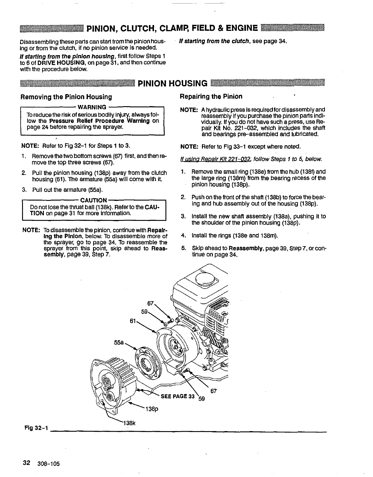
NOTE:
Refer to Fig 32-1 for Steps
1
to
3.
1.
Removethetwo bottom screws
(67)
first, andthen
re-
2. Pull the pinion housing (138p) away from the clutch
3. Pull
out
the armature (55a).
move the top three screws
(67).
housing (61).
me
armature (Sa) will come with it.
Do
not losethe thrust ball (138k). Referto the
CAU-
TlON
on page 31 for more information.
CAUTION
NOTE
To disassemble the pinion, continue with
Repalr-
ing the Plnlon,
below. To disassemble more of
the sprayer, go to page 34.
To
reassemble the
sprayer from this point, skip ahead to
Reas-
sembly,
page 39, Step
7.
Repairing the Pinion
NOTE
A
hydraulic press
isrequiredfordisassemblyand
vidually. If you do not have such a press, use
Re
reassembly If you purchase the pinion parts indi-
pair Kit
No.
221-032, which includes the shaft
and bearings pre-assembled and lubricated.
NOTE
Refer
to
Fig 33-1 except where noted.
If
usina
ReDair
Kit
221-032,
follow
Sreps
7
to
5,
below.
1.
2.
3.
4.
5.
Remove the small ring (138e) from
the
hub (1389 and
the large ring (138m) from the bearing recess
of
the
pinion housing (138p).
Push on the front of the shafl(l38b)
lo
force the bear-
ing
and hub assembly out of the housing (138~).
the shoulder
of
the pinion housing (138p).
Install the new shafl assembly (138a), pushing
it
to
,Install the rings (138e and 138m).
Skip ahead
to
Reassembly,
page 39, Step
7,
or con-
tinue on page 34.
Fig
32-1
32
308-105
 Loading...