308155 5
Installation
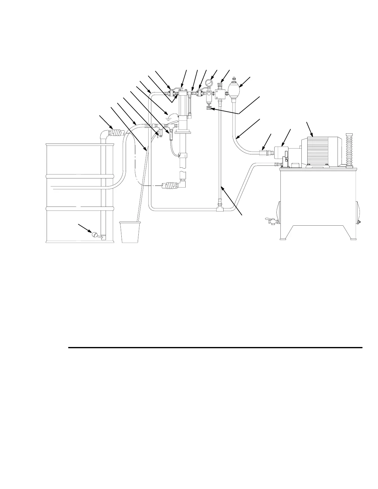
Fig. 1
KEY
A Suction hose
B Weep tube
C Fluid outlet line (to gun)
D Drain valve (required)
E Ground wire
F Hydraulic return line, minimum
3/4” I.D. (required)
G Hydraulic outlet, 1/2 npt
H Return line shut-off valve,
minimum 3/4” (required)
J Hydraulic inlet, 1/2 npt
K Tee, 3/4 npt
L* Supply line shut-off valve
M* Pressure gauge
N* Pressure reducing valve
(required in systems over 1500
psi [10 MPa, 102 bar])
P Accumulator
Q* Flow control valve
(required in systems over 3 gpm
[11 lpm])
R Hydraulic supply line
S Check valve
T Variable volume pressure
compensated pump
U Hydraulic power supply
W Drain line, accumulator
X Low-level cut-off valve
Y Thermal Relief Kit (required)
Part No. 237904
Typical Installation of a
Suction Feed System
A
B
C
D
E
F
G
H
JKLMN
P
Q
R
S
T
U
W
* Included in Hydraulic Fluid Control Kit 236864, which can be ordered separately.
X
Y
01843
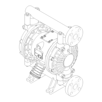
Although the installation shown in Fig. 1 is only a guide for selecting and installing system components and
accessories, some of the equipment is required, as noted in the key. For assistance in designing a system to suit
your needs, contact your Graco distributor.
Mount the pump to suit the type of installation planned.