OPERATION
Pressure Relief Procedure
WARNING
To reduce the risk of serious bodily injury, in
-
cluding injection; splashing in the eyes; injury
from moving parts or electric shock, always follow
this procedure whenever you shut
off
the sprayer,
when checking or servicing any part of the spray
system, when installing, cleaning or changing
spray tips, and whenever you stop spraying.
1.
Engage the gun safety latch.
2.
Turn the
ON/OFF
switch to
OFF.
3.
Unplug the power supply cord.
4.
Disengage the gun safety latch.
5.
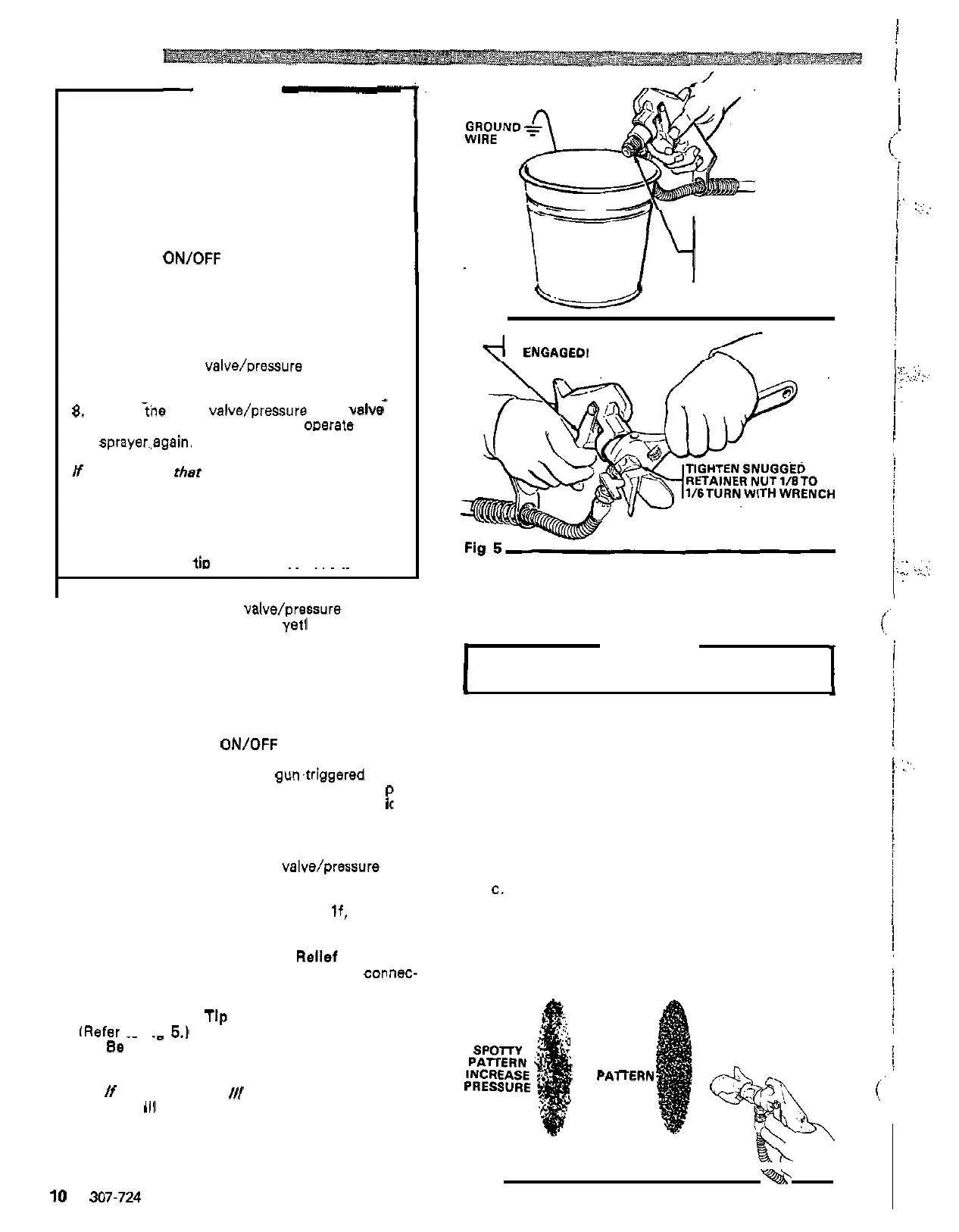
Hold
a
metal part of the gun firmly to the
side of
a
grounded metal pail, and trigger
the gun to relieve pressure.
6.
Engage the gun safety latch.
7.
Open the drain valve/Dressure relief valve.
having a container ready to catch the
drainage.
*
8.
Leave the drain valve/pressure relief Valve
sprayer..again.
open until you are readv to omrate the
If
you
suspect that the spray tip or hose is com-
pletely CLOGGED,
OR
THAT PRESSURE HAS
NOT BEEN FULLY RELIEVED after following the
steps above,
VERY SLOWLY loosen the tip guard
retaining nut or hose end coupling and relieve
pressure gradually. Then loosen the nut complete
-
ly. Now clear the
ti0
or hose obstruction.
~~ ~~ ~ ~~
Prima the Sprayer
with
Paint.
a.
Close
the filter drain valve/pressure relief valve.
b. Don't install the spray tip
yet1
c. Put the suction tube into the paint container.
d. Turn the pressure adjusting knob
all
the way
counterclockwise to lower the pressure setting.
e.
Disengage the gun safety latch.
f.
Hold
e
metal pert of the gun firmly against and
aimed into a grounded metal waste container.
See
Fig
4.
Squeeze
the trigger and hold
it
open, turn the
ON/OFF
switch to
ON,
and
slowly increase the pressure setting until the
sprayer starts. Keep the
gumtriggered until
all
air is forced out of the system and the aint
flows freely from the gun. Release the
tr
P
gger
and engage the safety.
NOTE:
If the pump is hard to prime, place
a
con
-
tainer under the drain valve/pressure relief
valve and open
it.
When fluid comes from
the valve, close
it.
Then disengage the gun
safety and proceed as in Step
If, above.
g. Check
all
fluid connections for leaks.
If
any are
found, follow the Pressure
Rellef
Procedure
tions.
Warning. above, before tightening
connec-
2.
Install the Spray
Tlp
and
Tip
Guard
fRefer
to
Fio
5.1
. ~ ~~
"
a.
Be
sure the gun safety latch
is
engaged.
b. Unscrew the retaining nut from the gun.
c. Install the spray tip.
.
.-
-..
If
using the RAC
Ill
Spray Tip Kit,
install the
Keep the packaging instructions for later
RAC
IO
spray housing, with the tip installed.
reference.
10
307-724
MAINTAIN FIRM
CONTACT BETWEEN
METAL
-
TO
-
METAL
GUNANOGROUNDED
METAL CONTAINER
Fig
4
u
BE SURE GUN
SAFETY
LATCH
IS
ENGAGED1
d. Tighten the retaining nut by hand until snug.
e.
Use
a
wrench to tighten the retaining nut about
1/8
to
1/6
turn.
Overtightening the retaining nut will damage the
CAUTION
seat gasket and result in leakage.
3.
Adjusting the Spray Pattern (Refer to Fig
6.1
a.
Increase
the
pressure adjusting knob setting
just until spray from the gun
is
completely
fogging, and to decrease tip wear and extend
atomized.. To avoid excessive overspray and
the life of the sprayer, always
use
the lowest
possible pressure needed to get the desired
results.
b. If more coverage
is
needed,
use
e
larger tip
rather than increasing the
pressure.
c.
Test the spray pattern. To adjust the direction
of the spray pattern, engage the gun safety
latch and loosen the retaining nut. Position the
tip
so
the groove
is
horizontal for
a
horizontal
tighten
the retaining nut.
pattern
or vertical for
a
vertical pattern. Then
GOOD
FULL
PARERN
Fig
6
-a'
I
1
I
I
.. .
. ,.,.
..
...
,.~
;
.,.
..
. ..
,
.,
_:
.:
,,.
.
:
...,
.. ..
..
,,.>.
.I
.:
...,.
..
..
.,
.
.
..
..
.
 Loading...