-
PRESSURE
CONTROL CALIBRATION
(See
Fig
25)
an injection injury or other serious bodily injury which can result from component rupture, electric shock, fire, ex.
USE EXTREME CAUTION WHEN PERFORMING THIS CALIBRATION PROCEDURE to reduce the risk
oi
plosion, or moving parts.
This procedure
sets
the sprayer to
2500
psi
1172
bar)
MAXIMUM WORKING PRESSURE. by performing these calibrations in any
other way.
NEVER attempt to increase the fluid outlet pressure
This procedure must be performed whenever
a
NEVER EXCEED
2500
psi
(172
bar) MAXIMUM
microswitch or pressure control assembly is removed sprayer
at
higher pressures could result in compo-
WORKING PRESSURE, Normal operation of the
and reinstalled or replaced to be sure
the sprayer is
properly calibrated.
nant rupture, fire or explosion.
Improper calibration can cause the sprayer to over-
ALWAYS
use
a
new
50
foot
(15.2
m) spray hose
pressurize and result in component rupture, fire or
rated for
3OOO
psi
1210
bar) MAXIMUM WORKING
explosion.
It
may
also
prevent the sprayer from ob-
PRESSURE when performing this procedure. A
taining the maximum working pressure which would
used,
underrated hose could develop
a
high pressure
leak or rupture.
result in poor sprayer performance.
AVOID touching the wire in the pressure control
reduce the risk of electric shock,
-.
assembly when the control box cover is removed to
Tools
Needed:
NEW
50
ft
(15.2
m)
3ooo
psi
(210
bar) airless spray
Needle Valve. Part No.
102
-
715
or
103-067
hose, Part No.
210
-
541
3/8"
open eid wrench
Fluid
-
Filled Pressure
Gauae.
Part No.
102-814
~~~ ~ ~ ~ ~~~~
".
5~gallon pail and water
Mineral Spirits (for flushing after test)
1.
Follow the Pressure Relief Procedure Warning
on page
14.
Install the new
50
ft
(15.2
m) spray
hose to the sprayer outlet. On the other end of
the
hose install the needle valve. Install the fluid
-
filled
pressure gauge in the top port of the fluid filter.
2.
Open the needle valve
slightly.
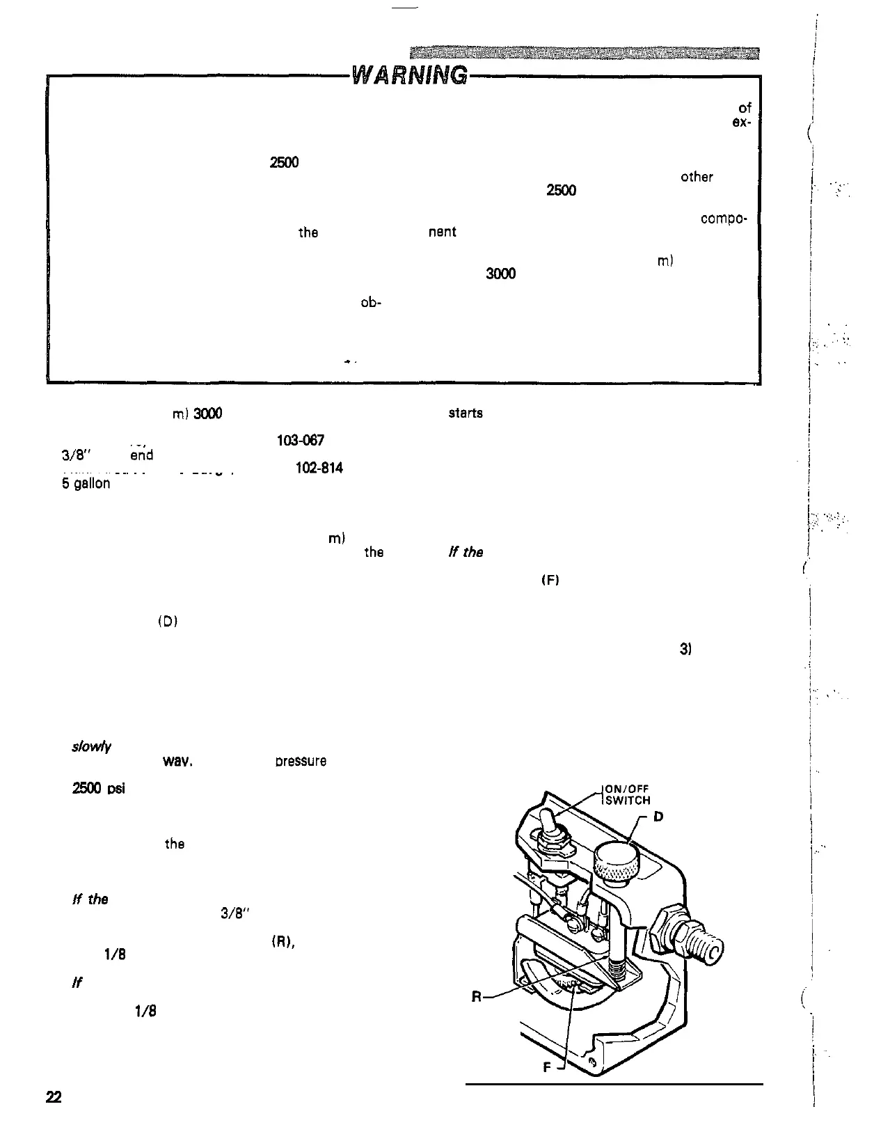
Turn the pressure
control knob
(D) to the minimum setting. Plug in
the sprayer and turn the switch ON. Increase the
pressure setting just enough to start the sprayer.
Prime the hose, being sure to eliminate
all
air from
the system.,
3.
Open the needle valve
a
little more
-
enough to.
allow the pump to run continuously
-
and turn the
slowly
start
to close the needle valve, but don't
pressure control knob to maximum. Now,
very
close
it
all
the way. Observe the Dressure
at
which
4.
Now check to
see
at
whet pressure the sprayer
starts to run again after stalling. Plug in the sprayer,
turn
it
on, close the needle valve, and set the
pressure
at
maximum. Allow the sprayer to run until
it
stalls.
5.
Now open the needle valve very slowly while ob-
serving the pressure gauge. Check to
see
if the
pressure drops to approximately
2100
psi
(147
bar)
before starting again.
N
the pressure
is
lower:
shut
off
and unplug the
sprayer, but do not relieve pressure. Turn the dif-
ferential wheel
(F)
counterclockwise
just one notch
end repeat Steps
4
and
5.
Check the pressure drop
again, and repeat if necessary.
NOTE:
If
you adjust the differential wheel, recheck
the stall pressure (steps
2
and
3)
to be sure
the
stall
pressure has not changed.
6.
Follow the Pressure Relief Procedure Wernlng
on page
14,
flush the water out with mineral spirits,
relieve pressure again, then remove the test hose,
needle valve and pressure gauge.
f
the pump stalls, 'which should
be
approximately
2500
psi
(172
bar).
NOTE:
The slower the pressure
is
brought up, the
easier
it
is
to note the exact
stall
pressure.
pressure to rise too
fast
which gives
a
false
Closing
the needle valve quickly causes the
reading.
N
the pressure
is
lower:
unplug the sprayer and
turn the pressure adjustment nut,
at
the bottom of
relieve pressure. Use
a
3/8"
open end wrench to
the pressure control knob shaft
IR),
counterclock
-
wise
1/8
turn or
less,
then repeat steps
2
and
3.
If the pressure
is
higher:
unplug the sprayer and
relieve pressure. Turn the pressure adjustment nut
clockwise
1/8
turn or
less
and repeat steps
2
and
3.
Repeat until the proper stall pressure is obtained.
22
307
-
724
R
Fig
25
yfl
..
..
,
...
,.
..
.
..
..
..
..
..
~.
....
..
.
..
..
,
.
.,.
'..
..
,.
.
.,,
~
.'
:
.
:.
..
:
...
..
..
..
.
..
,.
..
.
,
..
 Loading...