Component Identification
8 333182A
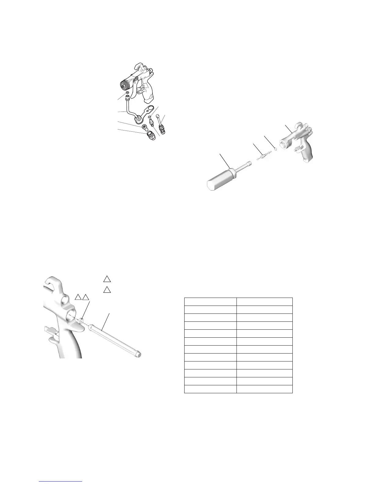
Fluid Tube Replacement (16)
1. Remove the air inlet fitting
(17) using the gun tool (30)
and remove the screw (20).
2. Unscrew the fluid inlet fitting
(25). Remove and clean or
replace the inline fluid filter
(24).
3. Unscrew fluid tube connector
(16a) from fluid inlet. Carefully
remove gasket (22).
Flat Tip Conversion Kit (Optional)
The Flat Tip Conversion Kit allows AAM Flat Tips to be used
with this gun. Order part number 288514.
Reassembly
1. Install the tube gasket (22) in the gun. Hand tighten the
fluid tube connector (16a) into the gun’s fluid inlet. Anti-
gens the air inlet fitting (17) and screw (20). Torque the
fluid tube connector to 150-160 in-lb (17-18 N•m). Torque
the air inlet fitting to 175-185 in-lb (20-21 N•m). Torque
the fluid tube bracket screw to 50-60 in-lb (6-7 N•m).
2. Install the inline fluid filter (24) into the base of the fluid
tube (16). Screw the fluid inlet fitting (25) into the base of
the tube. Torque to 175-185 in-lb (20-21 N•m).
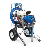
3. Place the new u-cup (7) on the seal installation tool (28),
with the u-cup lips facing the tool. Push the u-cup into the
back of the gun until you feel a definite snap.
4. Lubricate the front end of the air valve assembly (8).
Gently slide the air valve assembly into the back of the
gun, passing through the u-cup (7), as far as it will go. Be
careful not to damage the u-cup.
5. Slide the seat (10) onto the shaft (9). Be sure that the
tapered end of the seat is toward the thicker end of the
shaft. Carefully insert the shaft (9) and seat (10) in the air
valve (8).
6. Install the two springs (15 and 19). Screw the spring cap
(11) into the back of the gun body. Torque to 175-185
in-lb (20-21 N•m).
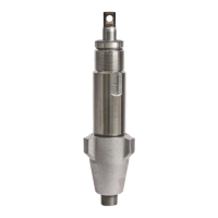
7. Lightly lubricate the needle assembly o-rings and shaft
where the packing slides. Be sure that the o-ring (2a) is in
place in the gun body (1).
8. Insert the fluid needle assembly (2) into the front of the
gun. Use the nut driver (29) to screw the fluid needle
assembly into the gun body (1) and torque to 50-60 in-lb
(6-7 N•m).
9. Install the trigger (3), pivot pin (13), and nut (14). Use low
strength thread locker and be sure that the brass piece of
the fluid needle assembly (2) is behind the trigger.
Lubricate both sides of the pivot pin where the trigger
contacts the pin and lubricate the boss on both sides of
the gun where the trigger contacts the gun body. Torque
the nut to 20-30 in-lb (2-3 N•m).
10. Trigger the gun to pull the needle back while you screw
the diffuser assembly (5) into the gun body (1) using the
gun tool (30). Torque to 155-165 in-lb (18-19 N•m). When
properly tightened, the flange will bottom out on the gun.
11. Attach the guard (6) and spray tip (33), page 5.
Translated Manuals
Translated manuals can be obtained from a distributor
or by visiting www.graco.com.
18
16
37
38
75
20
17
ti22690a
ti6578a
7
28
Lubricate lightly.
Lips face out of gun body.
3
8
3
8
Spanish - 333183 Estonian - 333195
French - 333184 Latvian - 333196
Dutch - 333185 Lithuanian - 333197
German - 333186 Polish - 333198
Italian - 333187 Hungarian - 333199
Turkish - 333188 Czech - 333200
Greek - 333189 Slovakian - 333201
Croatian - 333190 Portuguese - 333202
Danish - 333191 Finnish - 333203
Chinese - 333192 Swedish - 333204
Japanese - 333193 Norwegian - 333206
Korean - 333194 Russian - 333207
29
2
2a
1
ti6575a