K
Kayla ShieldsAug 16, 2025
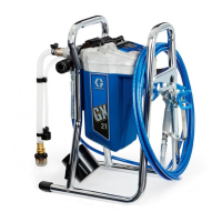
Why is my Graco GH Paint Sprayer spitting paint?
- RRichard DunlapAug 16, 2025
To resolve spitting from the Graco Paint Sprayer gun, check for loose connections on the siphon assembly and tighten them. Then, reprime the pump. Also, ensure that the fluid supply is not low or empty; if it is, refill the supply container. Another possible cause is a loose intake suction, in that case you need to tighten it.