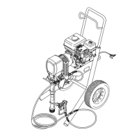
Installing the pump
WARNING
Seat the retaining spring (26) firmly
in the conecting
rod
groove to prevent the pin (25) from working loose
due
to vibration.
If
the pin works loose, it or other parts could break of
f
due
to the force of the pump action. These parts
could
be
projected through the air and result in serious inju
-
ry or property damage, including
the connecting rod
and bearing housing.
1. Screw
the
pump 3/4 of the way into the bearing hous
-
ing
(21). Hold the pin (25) up to the pin hole in the
con
-
necting
rod (22) and continue screwing in the
pump
until
the pin slides easily into the hole.
2. Align
the top threads of the pump cylinder flush
with
the
face of the bearing housing and so the outlet nip
-
ple
(57) is straight back.
3. Push
the retaining spring (26) into the groove of
the
connecting
rod, all the way around. T
ighten the lock
-
nut
(27) very tight – 70 ft–lb (95 N.m).
4. Tighten the packing nut (216) only enough to stop
leaking.
Fill the nut 1/2 full with Graco TSL.
5.
Assemble the remaining parts.
Fig. 17
25
26
27
22
21
0031A
1
2
Face
of bearing
housing
T
orque
to 70 ft–lb
(95 N.m)
2
1
Bearing
Housing & Connecting Rod
WARNING
To
reduce the risk of serious bodily injury always
follow the
Pressure Relief Procedure W
arning
on
page 2 before checking, adjusting, cleaning or
shutting down the sprayer
.
NOTE:
Steps 1 to 10 refer to Fig. 18.
1.
Remove the pump. See page 18.
2.
Remove the four screws (73) and lockwashers
(74) from the bearing housing (21).
3.
While pulling the connecting rod assembly (22)
with one hand, lightly tap the lower rear of the
bearing housing (21) with a plastic mallet to loosen
it from the drive housing (20). Pull the bearing
housing and the connecting rod assembly of
f the
drive housing.
4.
Inspect the crank (A) for excessive wear and re
-
place parts as needed.
5.
Evenly lubricate the inside of the bronze bearing
(C) in the bearing housing (21), and the inside of
the connecting rod link (D), with high–quality motor
oil. Liberally pack the roller bearing (E) in the con
-
necting rod assembly (22) with bearing grease.
6.
Assemble the connecting rod (22) and bearing
housing (21).
7.
Clean the mating surfaces of the bearing and drive
housings.
8.
Align the connecting rod with the crank (A). Align
the locating pins (F) in the drive housing (20) with
the holes in the bearing housing (21). Push the
bearing housing onto the drive housing or tap it
into place with a plastic mallet.
CAUTION
Use only
the locating pins (F) to align or seat the
bearing housing (21) with the drive housing (20).
9.
Install the screws (73) and lockwashers (74) on the
bearing housing. T
ighten the screws evenly to 175
in–lb (20 N.m).
10.
Install the pump. See above.
Fig. 18
73,74
F
C
59
26
57
27
28
30
24
11
A
21
E
D
22
25
68
101
102
103
20
1
Torque
to 175 in–lb
(20 N.m)
1
0149B

 Loading...