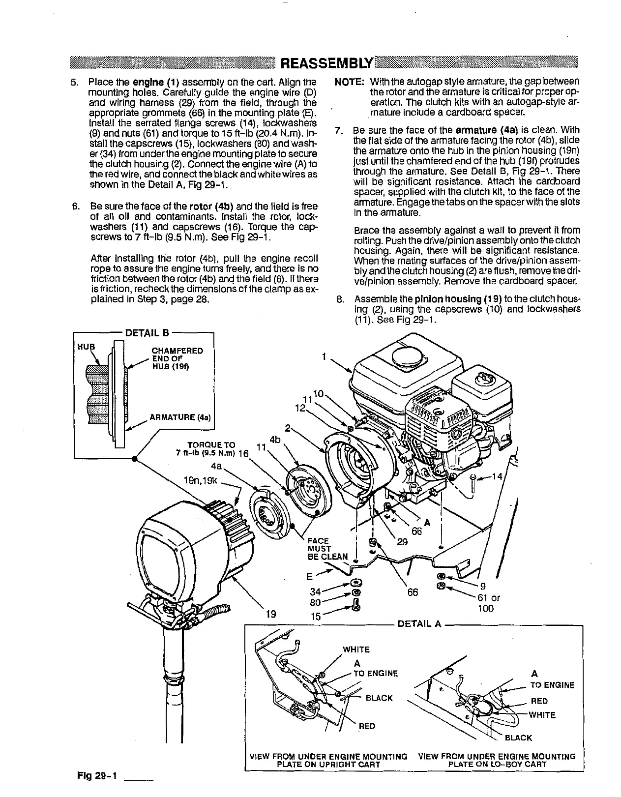
5.
Place the
engine
(1)
assembly on the cart. Align the
mounting holes. Carefully guide the engine wire (D)
and wiring harness (29) from the field, through the
appropriate grommets (66) in the mounting plate
(E).
Install the serrated flange screws (14), lockwashers
(9) and nuts (61) and torque to 15 fl-lb (20.4 Nm). In-
stall the capscrews (15), lockwashers (80) and wash-
er (34) from underthe engine mounting plate to secure
the clutch housing (2). Connect the enaine wire
IAl
to
the red wire, and connect the black aniwhite wiks'as
shown
in
the Detail
A,
Fig 29-1,
6.
Be
sure the face of the
rotor (4b)
and the field is free
washers (11) and capscrews (16). Torque the cap-
of all oil and contaminants. Install the rotor, lock-
screws to
7
fl-lb
(9.5
Nm).
See
Fig 29-1.
After installing ttie rotor (4b), pull the engine recoil
rope to assure the engine turns freely, and there
is
no
friction between the rotor
(4b)
and the field
(6).
If there
plained In Step
3,
page 28.
Is
friction, recheck the dimensions of the clamp as ex-
I
DETAIL B
-
NOTE:
With the autogap style armature, the gap between
the rotor and the armature is critical for proper op-
eration. The clutch kits with an autogap-style ar-
mature include a cardboard spacer.
7.
Be
sure the face of the
armature (48)
is clean. With
the flat side of the armature facing the rotor (4b), slide
the armature onto the hub in the pinion housing (19n)
just until the chamfered end of the hub (199 protrudes
through the armature.
See
Detail
B,
Fig 29-1. There
will be significant resistance. Attach the cardboard
spacer, supplied with the clutch kit, to the face of the
armature. Engage the tabson the spacerwith the slots
in the armature.
rolling. Push the drivdpinion assembly onto theclutch
Brace the assembly against a wall to prevent it from
When the mating surfaces of the drivelpinion assem-
housing. Again, there will be Significant resistance,
ve/pinion assembly. Remove the cardboard spacer.
bly and the clutch housing (2) are flush, remove the dri-
8. Assemble the plnlon housing
(1
9) to the clutch hous-
ing
(Z), using the capscrews (10) and lockwashers
(1 1). See Fig 29-1.
Flg 29-1
__
VIEW
FROM
UNDER ENGINE MOUNTING
VIEW
FROM
UNDER ENGINE MOUNTING
PLATE
ON
UPRIGHT CART PLATE ON
LO-BOY
CART