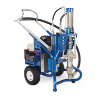
1. Install the clutch
houslng
(2),
capscrews (8) and
lockwashers (48) on the engine. See Fig 28-1.
2. Install the engine shaft
key
(13).
See Fig 28-1.
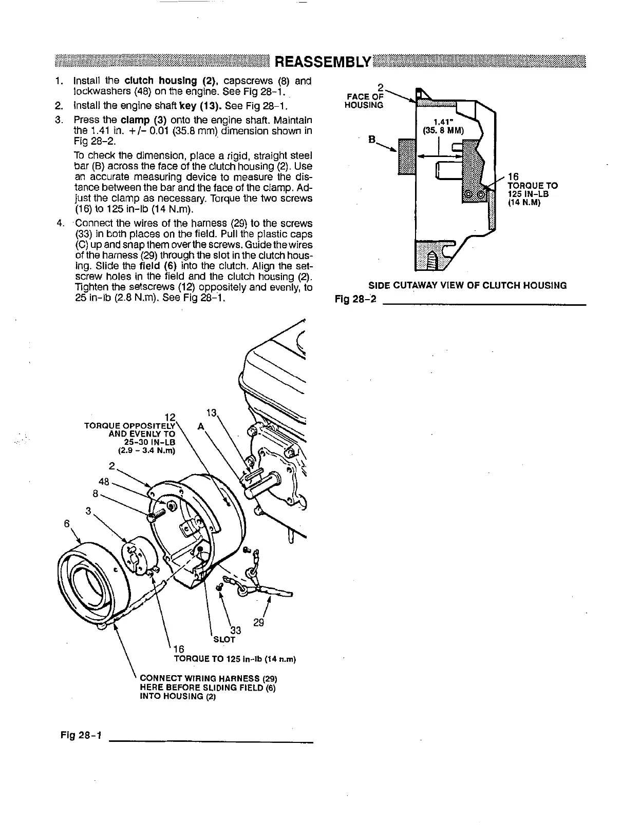
3.
Press the
clamp
(3)
onto the engine shaft. Maintain
the 1.41
in.
+/-
0.01 (35.8 mm) dimension shown in
Fig 28-2.
To check the dimension, place a rigid, straight steel
bar
(B)
across the face of the clutch housing (2). Use
an accurate measuring device
to
measure the dis-
tance between the bar and the face
of
the clamp. Ad-
just
the clamp as necessary. Torque the
two
screws
(16) to 125 in-lb (14 Nm).
4. .Connect the wires of the harness (29)
to
the screws
(33) in both places on the field. Pull the plastic caps
(C) up and snap them overthe screws. Guide thewires
of
the harness (29) through the slot in the clutch hous-
ing. Slide the
field
(6)
into the clutch. Align the
set-
Ighten the setscrews (12) oppositely and evenly, to
screw holes in the field and the clutch housing (2).
25 in-lb (2.8 N.m). See Fig 28-1.
16
TOROUE TO
125
IN-LB
(14
N.M)
SIDE
CUTAWAY VIEW
OF
CLUTCH HOUSING
Fig
28-'2
..
'
CONNECT WIRING HARNESS
(29)
HERE BEFORE SLIDING FIELD
(6)
INTO HOUSING
(2)
Fig
28-1