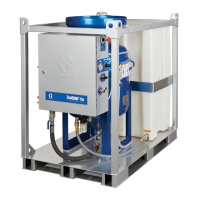
Component Identification
14 3A2797ZAA
Component Identification
Key for FIG. 2 and FIG. 3.
AA Advanced Display Module (see page 20)
BA Component A (Red) Pressure Relief Outlet
BB Component B (Blue) Pressure Relief Outlet
FA Component A (Red) Fluid Manifold Inlet (on left side of
manifold block)
FB Component B (Blue) Fluid Manifold Inlet
FM HFR Fluid Manifold
FP Feed Inlet Pressure Gauge
FT Feed Inlet Temperature Gauge
GA Component A (Red) Outlet Pressure Gauge
GB Component B (Blue) Outlet Pressure Gauge
HA Component A (Red) Hose Connection (from feed to gun
or mix head)
HB Component B (Blue) Hose Connection (from feed to gun
or mix head)
HP Hydraulic Power Pack Assembly
HT Hydraulic Tank
LS Pumpline Linear Sensor
MA Motor Control Module, see page 18
MP Main Power Switch
PA Component A (Red) Pump
PB Component B (Blue) Pump
PD Power Distribution Box
PHB Primary Heater - B Side
PHA Primary Heater - A Side
PI Primary Heater Fluid Inlet
PO Primary Heater Fluid Outlet
PR Primary Heater RTD
PS Primary Heater Overtemperature Switch
SA Component A (Red) PRESSURE RELIEF/DISPENSE
Valve
SB Component B (Blue) PRESSURE RELIEF/DISPENSE
Valve
TA Component A (Red) Pressure Transducer
TB Component B (Blue) Pressure Transducer
TC High Power Temperature Control Module (not shown, see
page 24)
FIG. 2: Component Identification, Heated Model shown with shrouds removed
PA
PB
FP
AA
HP
FM
PD
HT
MA
FP
FT
ti19508a

 Loading...