Conversion Kit Installation
14
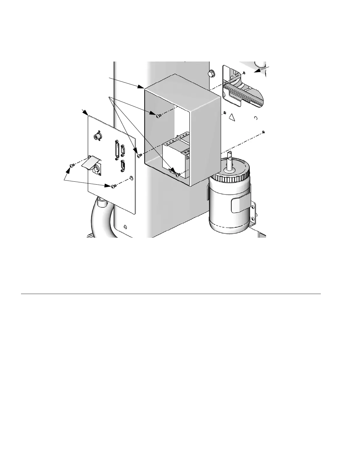
Install Electrical Enclosure
18. Remove three screws (DD) holding wire access
cover to the electrical cabinet.
19. Remove wire access cover from the left side of the
electrical cabinet (DF). The wire access cover will
not be re-used.
20. Remove electrical enclosure cover (DB) from the
electrical enclosure (DC) by removing two
screws (DA).
21. Pass wire harness from electrical enclosure
cover (DB) through back of electrical
enclosure (DC) and into electrical cabinet (DE).
22. Install electrical enclosure (DC) to side of electrical
cabinet (DE) using three screws (DD).
23. Install electrical enclosure cover (DB) to electrical
enclosure using two screws (DA).
F
IG. 8
DA
DB
DC
Key:
DA Screw
DB Electrical enclosure cover
DC Electrical enclosure
DD Wire access cover screws
DE Electrical cabinet
DD
DE
ti11757a
 Loading...