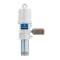
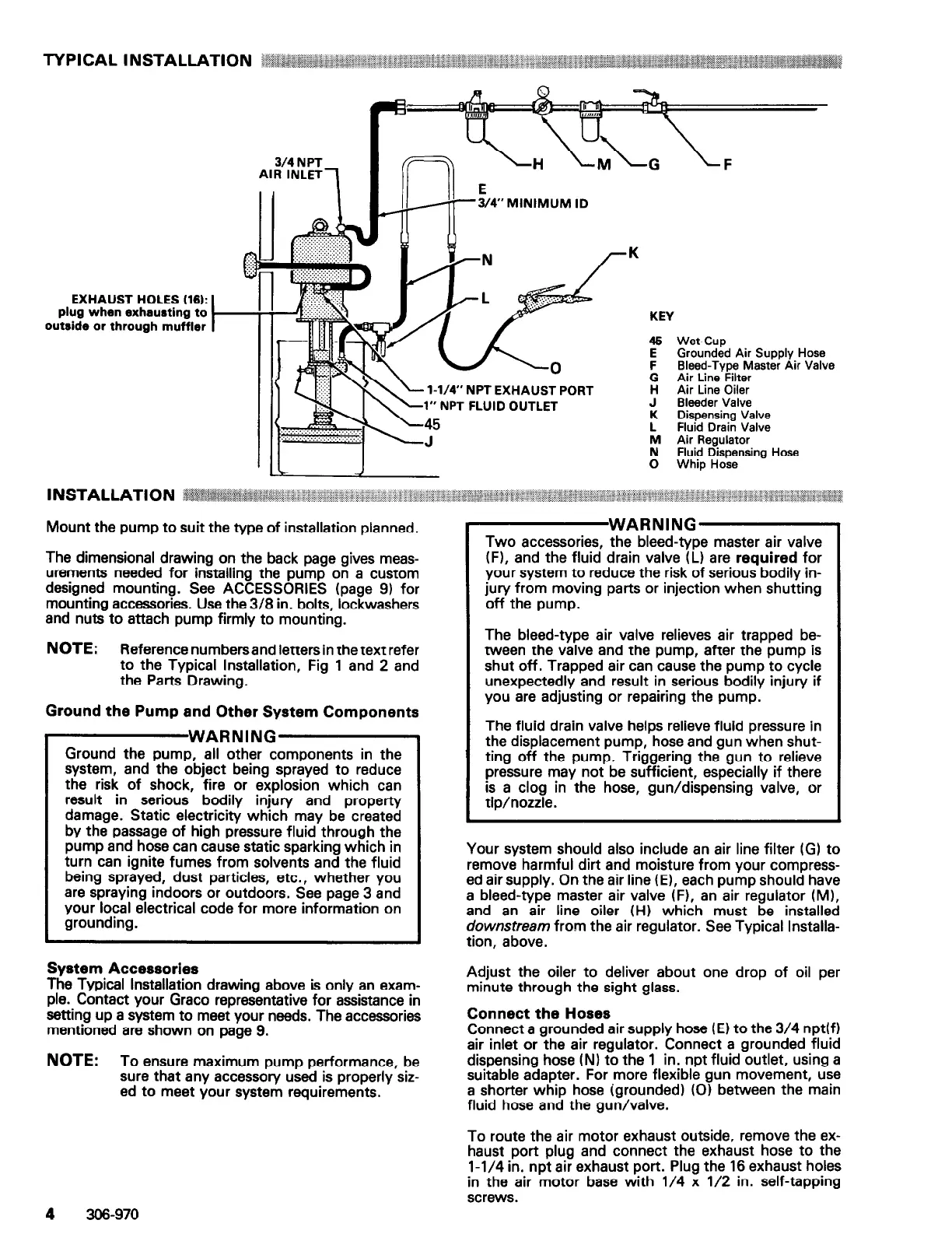
3/4” MINIMUM ID
EXHAUST HOLES (16):
plug when exhausting to
outside or through muffler
0
1-W” NPT
EXHAUST PORT
r FLUID
OUTLET
9’Ei%l Air Supply Hose
F Bleed-Type Master Air Valve
G Air Line Filter
H Air Line Oiler
J Bleeder Valve
K Dispensing Valve
L Fluid Drain Valve
M Air Regulator
N Fluid Dispensing Hose
0 Whip Hose
The dimensional drawing on the back page gives meas-
urements needed for installing the pump on a custom
designed mounting. See ACCESSORIES (page 9) for
mounting accessories. Use the 3/8 in. bolts, lockwashers
and nuts to attach pump firmly to mounting.
(F), and the fluid drain valve (L) are required for
your system to reduce the risk of serious bodily in-
jury from moving parts or injection when shutting
off the pump.
NOTE: Reference number-sand letters in the text refer
to the Typical Installation, Fig 1 and 2 and
the Parts Drawing.
Ground the Pump and Other System Components
WARNING
Ground the pump, all other components in the
system, and the object being sprayed to reduce
the risk of shock, fire or explosion which can
result in serious bodily injury and property
damage. Static electricity which may be created
by the passage of high pressure fluid through the
pump and hose can cause static sparking which in
turn can ignite fumes from solvents and the fluid
being sprayed, dust particles, etc., whether you
are spraying indoors or outdoors. See page 3 and
your local electrical code for more information on
grounding.
The bleed-type air valve relieves air trapped be-
tween the valve and the pump, after the pump is
shut off. Trapped air can cause the pump to cycle
unexpectedly and result in serious bodily injury if
you are adjusting or repairing the pump.
The fluid drain valve helps relieve fluid pressure in
the displacement pump, hose and gun when shut-
ting off the pump. Triggering the gun to relieve
pressure may not be sufficient, especially if there
is a clog in the hose, gun/dispensing valve, or
tip/nozzle.
Your system should also include an air line filter (G) to
remove harmful dirt and moisture from your compress-
ed air supply. On the air line (El, each pump should have
a bleed-type master air valve (F), an air regulator (MI,
and an air line oiler (HI which must be installed
downstream from the air regulator. See Typical Installa-
tion, above.
System Accessories
The Typical Installation drawing above is only an exam-
ple. Contact your Grace representative for assistance in
setting up a system to meet your needs. The accessories
mentioned are shown on page 9.
NOTE:
To ensure maximum pump performance, be
sure that any accessory used is properly siz-
ed to meet your system requirements.
4
306-970
Adjust the oiler to deliver about one drop of oil per
minute through the sight glass.
Connect the Hoses
Connect a grounded air supply hose (El to the 3/4 npt(f)
air inlet or the air regulator. Connect a grounded fluid
dispensing hose (N) to the 1 in. npt fluid outlet, using a
suitable adapter. For more flexible gun movement, use
a shorter whip hose (grounded) (0) between the main
fluid hose and the gun/valve.
To route the air motor exhaust outside, remove the ex-
haust port plug and connect the exhaust hose to the
l-1/4 in. npt air exhaust port. Plug the 16 exhaust holes
in the air motor base with l/4 x l/2 in. self-tapping
screws.
 Loading...