DISPLACEMENT PUMP SERVICE
Before you Start:
A. To reduce downtime, be sure you have all necessary re-
pair parts available. Recommended “tool box” spare
parts are listed in the parts list with an asterisk (“1.
6
B. Packing repair kit 210539 is available (see page 10).
If you have a repair kit, use all the new parts for the
best results. Parts included in the kit are marked with
a double asterisk, for example (28”“).
C. When cleaning parts, use a compatible solvent. In-
spect parts for wear or damage and replace as
necessary. Scoring or irregular surfaces on the
displacement rod (46) or smooth inner surface of the
displacement cylinder (27) causes premature packing
wear and leaking. Check these parts by rubbing a
finger on the surface or holding them up to the light
at a slight angle.
D. Use light, water-proof grease whenever grease is
mentioned.
Repair Procedure
1. Solvent flush the fluid from the pump if possible.
Follow the Pressure Relief Procedure on page 6.
Stop the pump at the bottom of its stroke.
2. Disconnect the hoses from the displacement pump.
Remove the pump from its mounting, and clamp it
in a vise.
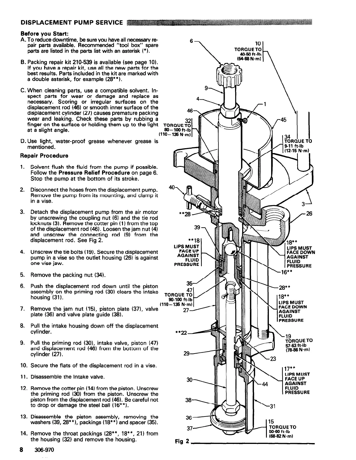
3. Detach the displacement pump from the air motor
by unscrewing the coupling nut (6) and the tie rod
locknuts (3). Remove the cotter pin (1) from the top
of the displacement rod (46). Loosen the jam nut (4)
and unscrew the connecting rod (9) from the
displacement rod. See Fig 2.
4. Unscrew the tie bolts (19). Secure the displacement
pump in a vise so the outlet housing (26) is against
one vise jaw.
5. Remove the packing nut (34).
6. Push the displacement rod down until the piston
assembly on the priming rod (30) clears the intake
housing (31).
39
7
“+18
LIPS MUST
FACE UP
AGAINST
FLUID
PRESSURE
TORQUE TO
(110-135 N.m)
7. Remove the jam nut (151, piston plate (371, valve
plate (36) and valve plate guide (38).
8. Pull the intake housing down off the displacement
cylinder.
9. Pull the priming rod (301, intake valve, piston (47)
and displacement rod (46) from the bottom of the
cylinder (27).
10. Secure the flats of the displacement rod in a vise.
**=A
29-
11. Disassemble the intake valve.
so\
12. Remove the cotter pin (14) from the piston. Unscrew
the priming rod (30) from the piston. Unscrew the
piston from the displacement rod (46). Be careful not
to drop or damage the steel ball (16”“).
38-
13. Disassemble the piston assembly, removing the
washers (39,28**1, packings (18”“) and spacer (351.
36-
37A
14. Remove the throat packings (28**, 18**, 21) from
. . . ,_^.
. . .
1
15
TORQUE TO
50-60 ft-lb
(W-S2 N.ml
\-19
TORQUE TO
R-63 ft-lb
(78-W N-m)
17**
WEMu;ST
AGAINST
FLUID
PRESSURE
the
hOuSIng
W;L) and remove the housing.
Fig 2
8 306-970