Pump
3A3951A 11
Assembly
7. Apply sealant (provided in kit) to valve threads.
Install valve stem assembly in pump manifold and
torque. See Pump Assembly Drawing page 8 for
torque.
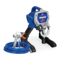
8. Install base (C) on valve, aligning pin (E) on base
(C) with hole (F) on pump housing (1).
9. Rotate valve stem with a pin punch until hole is per-
pendicular.
10. Install knob (A) over base (C).
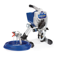
11. Place knob in SPRAY position.
12. Insert end of pin punch through hole in knob (A), to
make sure knob and valve stem are aligned.
13. Install pin (B) through hole in knob (A). Tap pin
through knob with hammer. End of pin will be flush
with top of hole in knob when correctly installed.
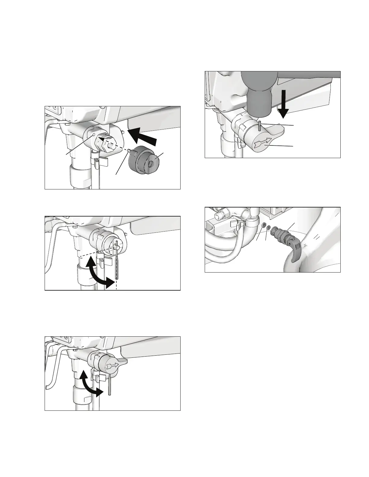
GX Models Only
1. Remove valve stem assembly (D) from pump
housing (1). Make certain gasket (H) and seat (G) do
not stay in pump housing (1).
2. Apply sealant (provided in kit) to valve threads.
Install valve stem assembly in pump housing (1)
and torque. See Pump Assembly Drawing for
torque.
Pump Outlet Valve Replacement
Disassembly
1. Perform Pressure Relief Procedure, on page 1.
2. Unplug sprayer.
3. Remove outlet valve (15) from pump housing (1).
4. Clean all dried residue from around pump outlet
seat area in pump housing (1).
Assembly
1. Verify that O-rings are installed.
2. Thread new pump outlet valve (15) into pump hous-
ing (1). Torque, see Pump Assembly Drawing
page 8 for torque.
ti11877b
ti11878b
GH
D
 Loading...