Drive
3A3951A 5
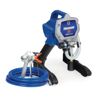
e. Position the push nut and socket at the end of
the motor shaft. Use a small or light (8 oz./225g)
hammer to drive the push nut (54b) onto the
shaft.
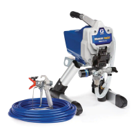
5. Clutch Fan Replacement
a. Pry push nut (54b) off the motor shaft with a
small screwdriver.
b. Remove and discard old push nut (54b), washer
(54c), fan, and shaft adapter (54d). Shaft
adapter requires a 5/64” hex key to loosen the
setscrew. The application of heat is required to
loosen the setscrew.
c. Slide the new shaft adapter (54d) on to the
motor shaft. Apply thread locker (supplied in kit)
to setscrew. Thread setscrew into shaft adapter
(54d) and torque to 20-25 in-lb (2.3 - 2.8 N•m).
d. Rotate fan clockwise while sliding fan onto shaft
adapter (54d) with the fins facing the motor.
Slide wave washer (54c) onto motor shaft.
e. Place a push nut (54b) on a 3/8” or 10mm
socket.
f. Position the push nut and socket at the end of
the motor shaft. Use a small or light (8 oz./225g)
hammer to drive the push nut onto the shaft
compressing the wave washer.
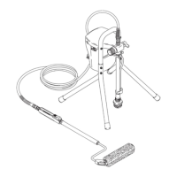
6. Slide motor shield (8) over the motor.
7. Secure the motor shield (8) using the two machine
screws (12) removed earlier.
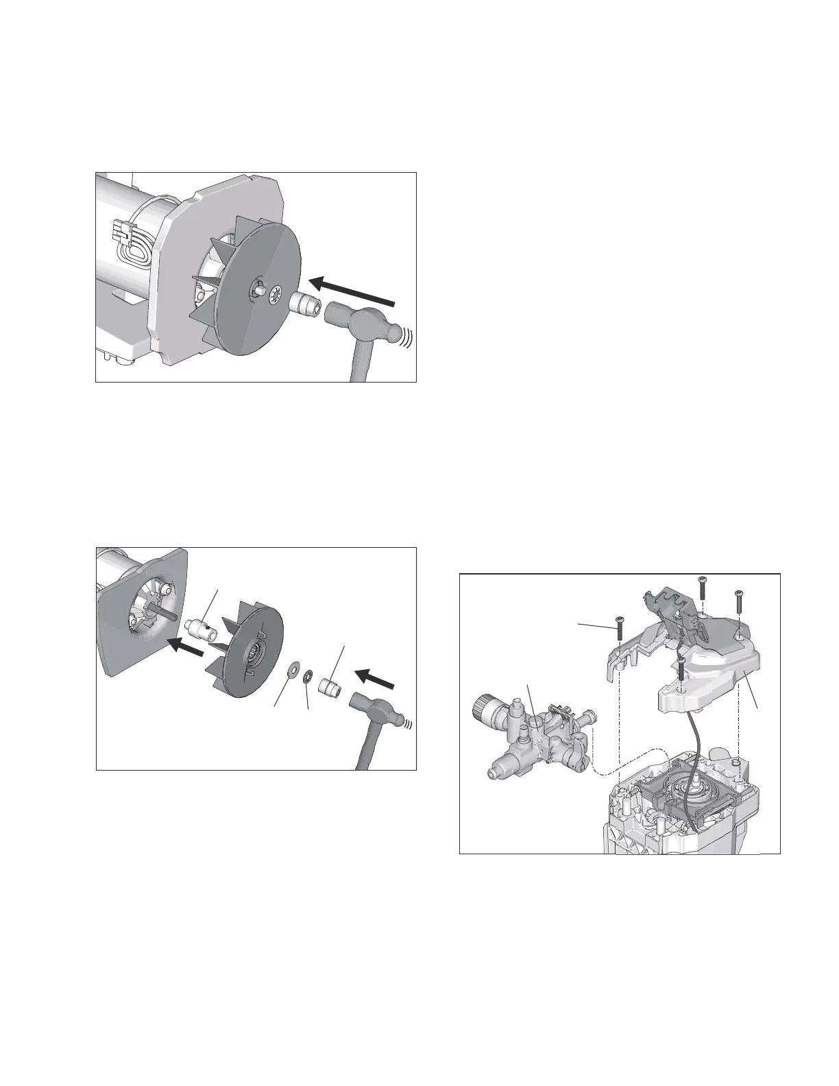
Gear & Yoke Replacement
Disassembly
1. Perform Pressure Relief Procedure, on page 1.
2. Unplug sprayer.
3. If necessary remove paint shield (14). Paint shield is
not included on all models.
4. Position sprayer so front cover (10) is pointing up.
5. Open Easy Access Door page 9.
6. Remove four front cover (10) screws (12) using a
T-30 Torx. Move front cover (10) to the side, support
cover so that it is not hanging by the cable.
7. Remove pump assembly (7) by sliding it off the
mounting pins. Set the pump assembly to the side.
ti28541a
ti28542a
54d
54c
54b
3/8" or 10mm
socket
7
12
10
 Loading...