Drive
6 3A3951A
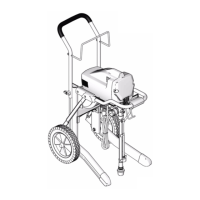
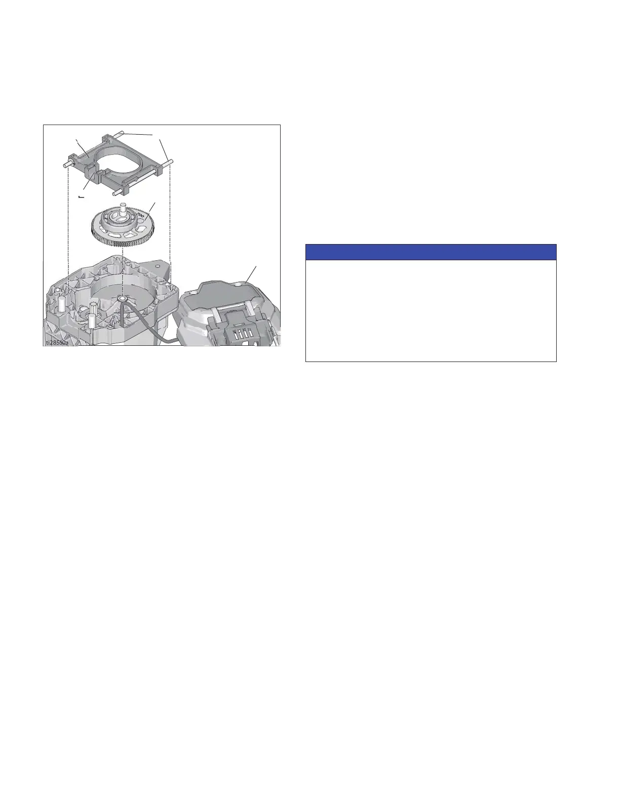
8. Remove yoke (D) with the two yoke guide rods (C)
from the drive housing.
9. Remove gear (A) from drive housing.
Assembly
1. Use applicator brush to spread entire contents of
grease tube (included in kit) into gear teeth. Grease
must be worked into roots of gear teeth to ensure
long life.
2. Carefully position new gear (A) in drive housing.
Make certain motor drive gear meshes with new
gear (A).
3. Install yoke (D) with slot (E) facing out for pump pis-
ton as shown.
4. Apply grease to yoke guide rods (C).
5. Install front cover (10) and cover screws (12).
6. Install pump assembly and close easy access door.
See Pressure Control Replacement page 9
Assembly for details.
CD
A
10
E
NOTICE
If yoke guide rods (C) drop out of position during
assembly, damage to cover will occur when cover is
tightened. Always check position of guide rods before
tightening cover.
Take care to not pinch wiring harness (10c) between
pump drive housing and between front cover (10). To
prevent wiring harness damage, use a needle-nose
pliers to move harness.
 Loading...