Do you have a question about the Graco Mark V Premium and is the answer not in the manual?
Details proper electrical grounding procedures and safe use of extension cords.
Instructions to prevent ignition from flammable fumes, static electricity, and open flames.
Warns about high-pressure fluid injection and the need for immediate medical treatment.
Covers hazards from improper equipment use, fatigue, drugs, and electric shock risks.
Addresses risks from pressurized aluminum parts and hazards posed by moving machinery components.
Details essential protective gear required for safe operation and servicing of the equipment.
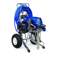
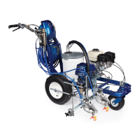
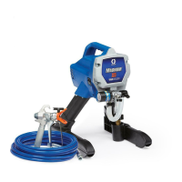
Identifies and labels the main parts of the sprayer system using numbered diagrams.
Explains grounding for safety and the use of conductive pails with fluids.
Describes the motor's thermal overload switch and how it affects operation.
Provides a step-by-step guide to safely relieve pressure before maintenance or cleaning.
Diagnoses and resolves issues related to low pump output, leaks, and worn components.
Addresses problems caused by clogged filters, faulty prime valves, and packing issues.
Troubleshoots motor issues, excessive leakage, spitting fluid, and priming difficulties.
Diagnoses issues with the digital display, connections, and general sprayer operation.
Addresses issues where the sprayer does not run or the digital display is blank.
Guides through diagnosing and resolving error code E=02 related to transducer issues.
Guides through diagnosing and fixing error code E=03, indicating a missing pressure signal.
Details troubleshooting steps for error E=05, indicating the motor shaft is not rotating.
Procedure to test for shorts in the motor field connector to diagnose E=05 errors.
Instructions to check the motor thermal switch resistance for error code E=05.
Diagnoses error E=06 related to motor overheating or blocked air intake.
Steps to resolve error E=09 caused by a missing motor position sensor signal.
Troubleshoots error E=10, indicating the control board may be overheating.
Visual guide to diagnose why the sprayer will not run, covering power, switches, and motor.
Guides for checking voltage, ON/OFF switch, and motor thermal switch for 110V models.
Instructions on disconnecting the potentiometer for troubleshooting 110V sprayer issues.
Guides for checking voltage, ON/OFF switch, and motor thermal switch for 230V models.
Instructions on disconnecting the potentiometer for troubleshooting 230V sprayer issues.
Procedure to diagnose why the sprayer fails to shut off, checking pressure and transducer.
Detailed steps for safely removing the motor control board from the sprayer unit.
Instructions for installing a new motor control board, including thermal paste application.
Steps for removing the filter board, including disconnecting various connectors.
Guidance on installing the filter board and reconnecting necessary components.
Instructions for removing the pressure adjust potentiometer from the control panel.
Guidance on installing the new pressure adjust potentiometer and reassembling the panel.
Detailed steps for safely disconnecting and removing the pressure control transducer.
Instructions for installing the pressure control transducer and reconnecting wiring.
Procedures for removing the drive housing, emphasizing caution with the gear cluster.
Guidance on installing the bearing housing and drive housing components.
Steps for disconnecting and removing the sprayer motor.
Instructions for installing a new motor, connecting wiring, and securing components.
Detailed instructions for safely removing the displacement pump assembly.
Guidance on installing the new displacement pump, ensuring proper pin and hose connections.
Instructions for disassembling and removing the hose reel unit.
Guidance on greasing, installing washers, and reassembling the hose reel components.
Steps for removing the fast flush switch from the control panel and board.
Instructions for installing the new fast flush switch and reconnecting wiring.
Visual representation of electrical component connections for 230V sprayer models.
Visual representation of electrical component connections for 110V sprayer models.
Blank space for users to record important notes during maintenance or troubleshooting.
Provides additional space for users to document service details, observations, or reminders.
Details Graco's warranty coverage, limitations, exclusions, and claim procedures.
Information on obtaining the latest product details, patent information, and placing orders.
| Hose Length | 50 ft |
|---|---|
| Power Source | Electric |
| Voltage | 120 V |
| Type | Airless |
| Horsepower | 1.5 HP |
| Motor Type | Brushless DC |