Filter Board
3A2333B 23
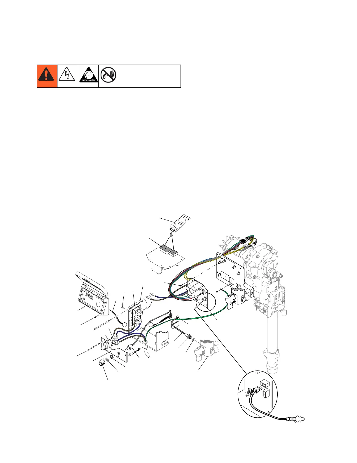
Filter Board
Removal
1. Perform Pressure Relief Procedure; page 9. Wait 5
minutes before servicing.
2. Remove four screws (38) and cover (96).
3. Disconnect display connector (A) from motor control
board (52).
4. Remove bottom two screws (39). disconnect potenti-
ometer connector from motor control board (52). Dis-
connect power cord connectors (D) and filter board
connectors from ON/OFF switch (33) and remove con-
trol panel (68).
5. Disconnect Fast Flush switch connector from motor
control board.
6. Disconnect motor control board power connectors from
filter board (146).
7. Remove four screws from filter board (146).
Installation
NOTE: See Wiring Diagram (page 36) for locations of wire
connections.
1. Install filter board (146) with four screws (163).
2. Connect motor control board power connectors to filter
board (146).
3. Connect filter board power connectors (J) to top two
terminals of ON/OFF switch (33) and power cord con-
nectors (D) to bottom two terminals of ON/OFF switch.
4. Connect potentiometer connector to motor control
board (52).
5. Connect Fast Flush switch connector to motor control
board.
6. Install control panel (68) with two screws (39).
7. Connect display connector (A) to motor control board
(52).
8. Install cover (96) with four screws (38).
A
A
Fast Flush
5
52
61
A
96
38
39
68
34
115
82
82
E
20
80
67
E
27
52
D
33
146
ti18442a
163