Repair
Note
Use drop cloth o r rags to protect Reactor
and surrounding areas from spills.
Note
Steps 9–11 apply to pump A. To
disconnect pump B, go to steps 12 and
13.
9. Disconnect fittings at fluid inlet (C) and outlet (D).
Also disco nne ct steel outlet tube from h eate r
inlet.
10. Disconnect
tubes (T). Rem ov e bo th tube fittin gs
(U) from wet
-cup.
11. Loosen locknut (G) by h itting firmly with a
non-sparking hammer. Unscrew pump far
enough to expose rod retaining pin. Push
retaining wire clip up. Push pin out. Continue
unscrewing pump.
Pump A
Figure 3
1
Flat side faces up.
2
Lubricate threads with ISO oil or grease.
3
Pump top threads must be nearly flush with
bearing face (N).
Note
Steps 12 and 13 apply to pum p B.
12. Disconnect fluid inlet (C) and outle t (D). Also
disconnect steel outlet tube from heater inlet.
13. Push retaining wire clip (E) up. Push pin (F)
out. Loos en loc kn ut (G) b y hi tting firm ly with a
non-sparking hammer. Unscrew pump.
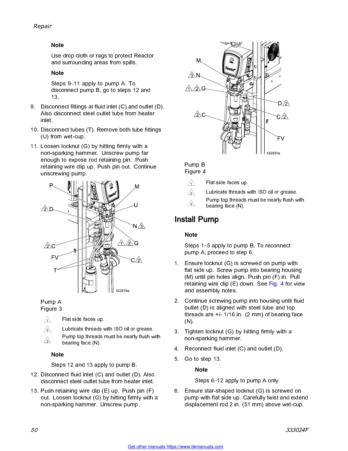
Pump B
Figure 4
1
Flat side faces up.
2
Lubricat
e threads with ISO oil or grease.
3
Pump top threads must be nearly flush with
bearing face (N).
Install Pump
Note
Steps 1–5 apply to pump B. To reconnect
pump A, proceed to step 6.
1. Ensure locknut (G) is screwed on pump with
flat side up. Screw pump i nto bearing housing
(M) until pin holes align. Push pin (F) in. Pull
retaining wire clip (E) down. See Fig. 4 fo r v iew
and assembly notes.
2. Continue screwing pump into housing until fluid
outlet (D) is aligned with steel tube and top
threads are +/- 1/16 in. (2 mm) of bearing face
(N).
3. Tighten l oc k nut (G) b y hitting fi rmly with a
non-sparking hammer.
4. Reconnect fluid inlet (C) and outlet (D).
5. Go to step 13.
Note
Steps 6–12 apply to pump A only.
6. Ensure star-shaped locknut (G) is screwed on
pump with flat side up. Carefully twist and extend
displ ac eme nt rod 2 in. (51 mm) abov e wet-c up.
50 333024F
Get other manuals https://www.bkmanuals.com