earing
Housing
and
Connecting
Rod
Replacement
(Fig.
19)
Ihl
FLUID
INJECTION
HAZARD
To reduce the risk of serious injury,
follow the illustrated
Pressure
Relief
I
Procedure
warning on page
12
when-
ever you are instructed to relieve pressure.
NOTE:
Read the GENERAL REPAIR INFORMATION on
page
18
before doing this procedure.
NOTE
Stop the sprayer at the bottom of its stroke to
get the crank (E) in its lowest position.To lower
the crank manually, carefully rotate the blades
of the fan with a screwdriver.
1.
Relieve pressure.
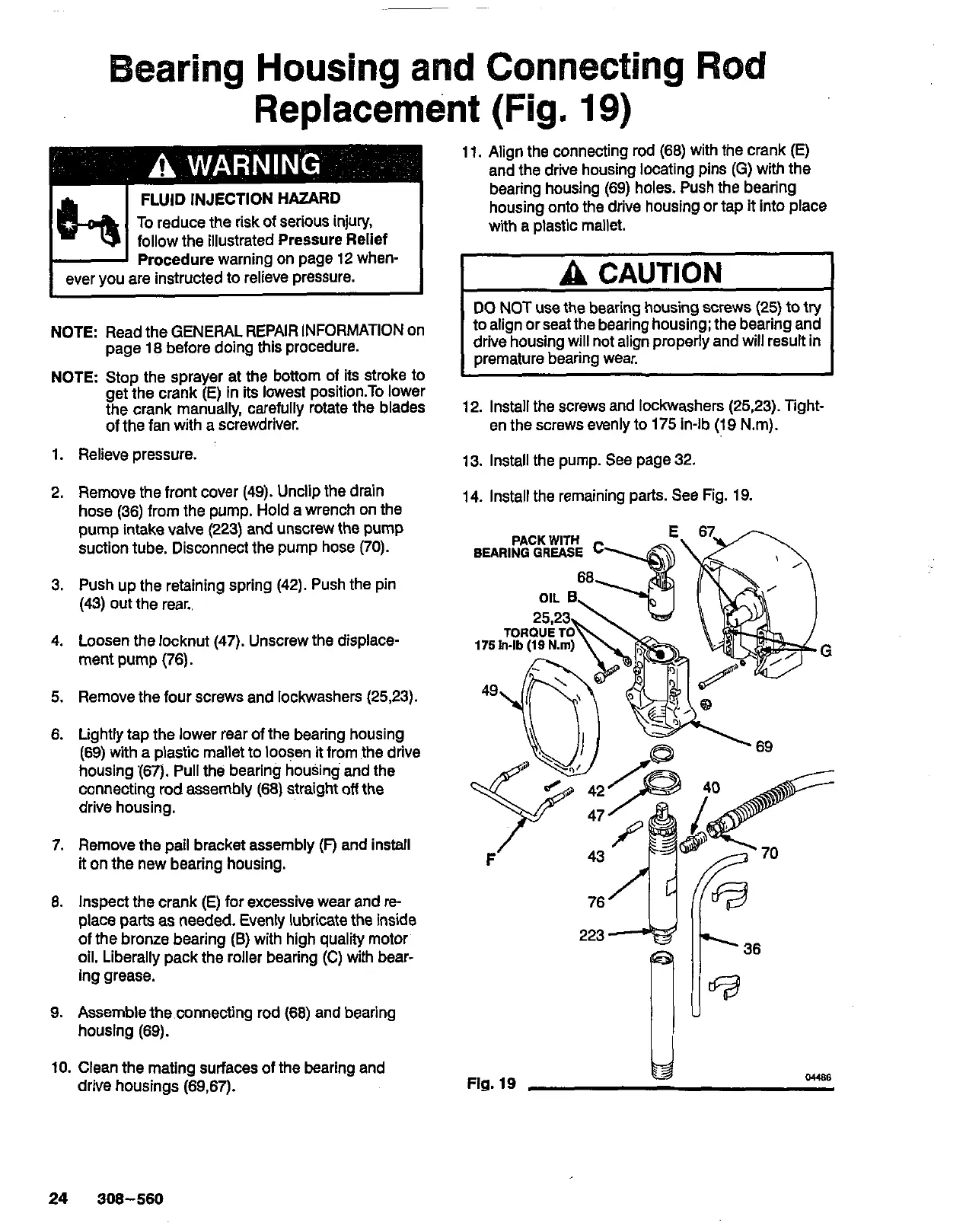
2.
Remove the front cover
(49).
Unclip the drain
hose
(36)
from the pump.
Hold
a wrench on the
pump intake valve
(223)
and unscrew the pump
suction tube. Disconnect the pump hose
(70).
3.
Push up the retaining spring
(42).
Push the pin
(43)
out the rear..
4.
Loosen the locknut
(47).
Unscrew the displace-
ment pump
(76).
5.
Remove the four screws and lockwashers
(25,23).
6.
Lightly tap the lower rear
of
the bearing housing
housing 167).
Pull
the bearing housing and the
(69)
with a plastic mallet to loosen it from the drive
connecting rod assembly (68) straight
off
the
drive housing.
7.
Remove the pail bracket assembly
(F)
and install
it on the new bearing housing.
8.
Inspect the crank (E) for excessive wear and re-
of the bronze bearing
(B)
with high quality motor'
place parts as needed. Evenly lubricate the inside
oil. Liberally pack the roller bearing (C) with bear-
ing grease.
9.
Assemble the connecting rod (68) and bearing
housing
(69).
10.
Clean the mating surfaces of the bearing and
drive housings
(69,67).
11.
Align the connecting rod (68) with the crank (E)
and the drive housing locating pins
(G)
with the
bearing housing
(69)
holes. Push the bearing
housing onto the drive housing or tap
it
into place
with a plastic mallet.
I
A
CAUTION
1
to align or seat the bearing housing; the bearing and
DO
NOT
use the bearing housing screws
(25)
to try
drive housing will not align properly and will result in
oremature bearina wear.
12.
Install the screws and lockwashers
(2523).
Tight-
en the screws evenly to
175
in-lb
(19
Nm).
13.
Install the pump. See page
32.
14.
Install the remaining parts. See Fig.
19.
G
\
II
I
223
Fig.
19
we
24
308-560