P a g e | 7
TYPICAL NETWORK TOPOLOGY
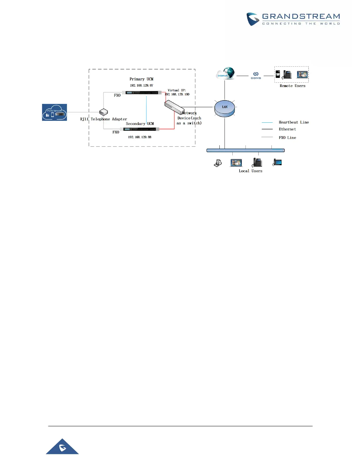
Figure 1: Typical Network Topology
The two UCM in High Availability setup must be deployed in the same location and connected directly to
each other via heartbeat port on each UCM. The primary UCM and secondary UCM can be connected to
each other via a straight-through Ethernet cable on the heartbeat port. For each UCM, connect its WAN or
LAN port to the uplink network device. For FXO port, an RJ11 telephone adapter is required to split the
PSTN line connection into two ports for each UCM’s FXO port to connect to.
 Loading...