Page 21Section 6: Commissioning, Draining Down and Safety
6.6 POTABLE HOT WATER EXPANSION
VESSEL
1. The potable hot water expansion vessel is connected into
the cold water supply to the cylinder. Refer to Figure 2-2 for
position.
! NOTE !
No valve should be tted between the expansion vessel
and the supply pipe.
2. Ensure that the air charge in the vessel matches the
pressure setting shown on the pressure reducing valve.
3. The expansion vessel must be installed even if an
accumulator is tted.
4. The charge of the vessel must be checked at every annual
service.
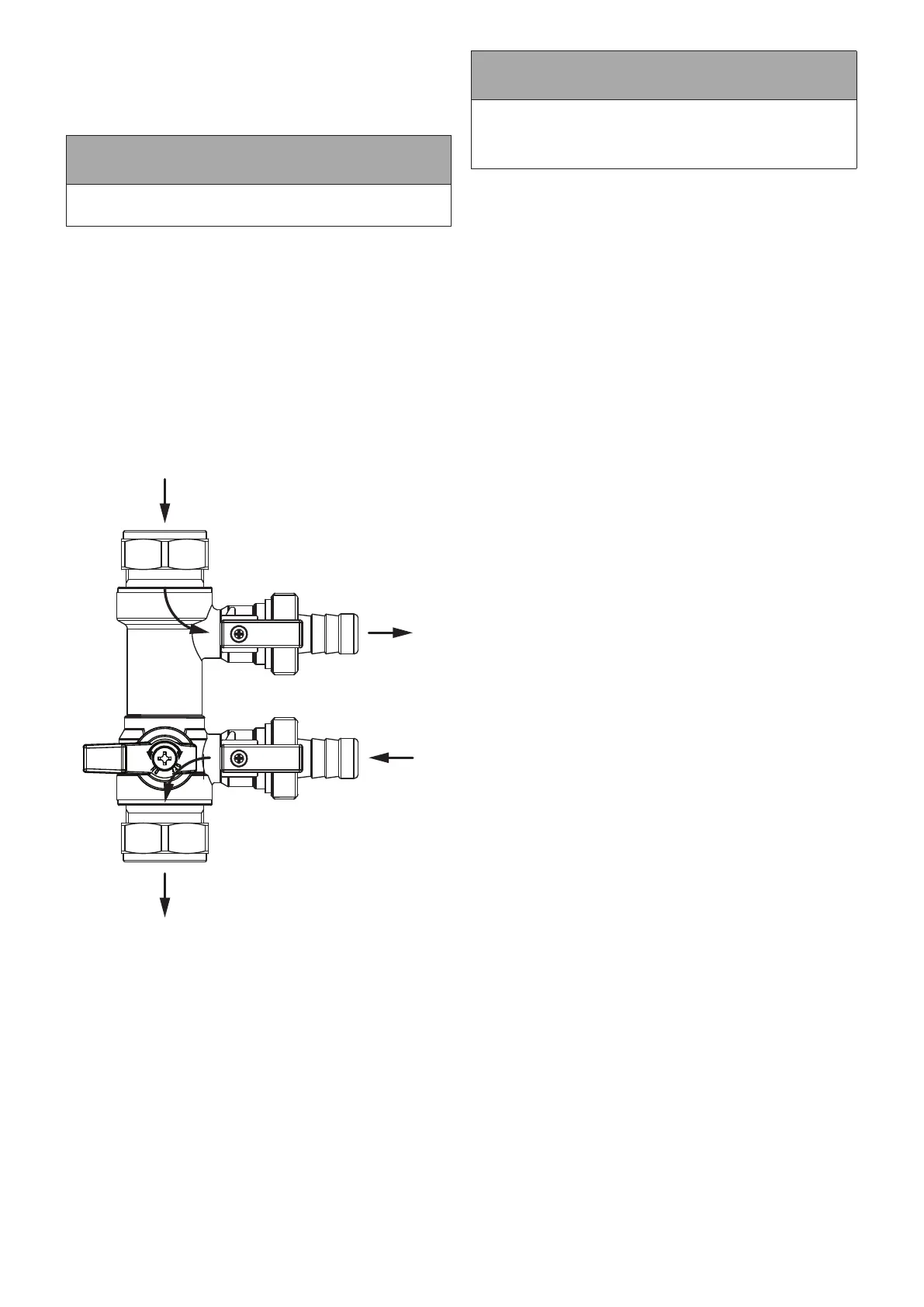
6.7 FILL & FLUSH VALVE
A primary circuit ll & ush valve is factory tted to the ow pipe
to the indirect cylinder coil, below the DHW zone valve. Refer to
Figure 2-2 for location and Figure 6-1 for a more detailed image.
1
2
ASHP
Flow to
Fill
Figure 6-1: Fill and ush valve
This ll & ush valve can be used to ll and ush the primary
circuit, and can also be used to add system additives (such as
glycol, corrosion inhibitor, etc...) to the primary circuit. These
processes are described in Sections 6.7.1 to 6.7.3.
6.7.1 FLUSHING THE SYSTEM
To ush the system:
1. Using the hose connectors provided, connect a hose to the
lling connection and a hose to the drain connection. Refer to
Figure 6-1.
! NOTE !
If the ll connection (see Figure 6-1) is connected to the
mains water supply, ensure a non-return valve is tted to
prevent the contents of the heating system syphoning into
the mains supply.
2. Close valves 2 & 3 (see Figure 6-1). A valve is closed when
the lever is at right angles to the ow of water.
3. Open valve 1 (see Figure 6-1). A valve is open when the
lever is in-line with the ow of water.
4. Open any manual air vents on the primary circuit.
5. Ensure any 2-port zone valves on the system are open.
6. Gradually add the appropriate amount of ushing solution to
the system via the lling connection.
7. Using the lling loop factory tted to the cylinder, ll the
system until all air has been purged (refer to Figure 2-2 for
component locations).
8. Close any manual air vents on the primary circuit.
9. Open valve 3 (see Figure 6-1).
10. Close valve 1 (see Figure 6-1).
11. Pressurise the system to the intended cold ll pressure Using
the lling loop and system pressure gauge factory tted to
the cylinder (refer to Figure 2-2 for component locations).
12. Clean the system according to the procedure outlined by the
ushing solution manufacturer.
13. Close valve 3 (see Figure 6-1).
14. Open valve 2 (see Figure 6-1) and allow the system to drain.
6.7.2 SYSTEM ADDITIVES
To ll & ush valve can be used to include additives (such as
glycol, corrosion inhibitor, etc...) to the system.
To do this:
1. Connect a hose to the lling connection. Refer to Figure 6-1.
2. Ensure valves 2 & 3 (see Figure 6-1) are closed. A valve is
closed when the lever is at right angles to the ow of water.
3. Open valve 1 (see Figure 6-1). A valve is open when the
lever is in-line with the ow of water.
4. Open any manual air vents on the primary circuit.
5. Ensure any 2-port zone valves on the system are open.
6. Gradually add the required quantity of each additive to the
system via the lling connection.
7. Using the lling loop factory tted to the cylinder, ll the
system until all air has been purged (refer to Figure 2-2 for
component locations).
8. Close any manual air vents on the primary circuit.
9. Open valve 3 (see Figure 6-1).
10. Close valve 1 and disconnect the hose from the lling
connection (see Figure 6-1).
11. Pressurise the system to the intended cold ll pressure Using
the lling loop and system pressure gauge factory tted to
the cylinder (refer to Figure 2-2 for component locations).
6.7.3 DRAINING THE SYSTEM
To drain the system:
1. Connect a hose to the drain connection (see Figure 6-1) and
terminate the hose in a suitable location.
2. Close valve 3 (see Figure 6-1). A valve is closed when the
lever is at right angles to the ow of water.
3. Ensure any 2-port zone valves on the system are open.
4. Open valve 2 (see Figure 6-1) and allow the system to drain.