Section 3: Primary Circuit InstallationPage 10
3.1 GRANT QR INTEGRATED INDIRECT
HEAT PUMP CYLINDERS
Grant QR integrated indirect heat pump cylinders are specically
designed for connection to most fully pumped Air Source Heat
Pump systems (such as the Grant Aerona³ Heat Pump range) -
either open vented or sealed systems having a maximum working
pressure of 3.5 bar and a maximum working temperature of 90ºC.
If you are in any doubt over the suitability of an Air Source Heat
Pump (other than a Grant Aerona³ heat pump) for use with the
cylinder, consult the heat pump manufacturer.
! WARNING !
Solid fuel or wood burning boilers and gravity circulation
systems must not be used on the primary circuit of an
unvented hot water system.
3 PRIMARY CIRCUIT INSTALLATION
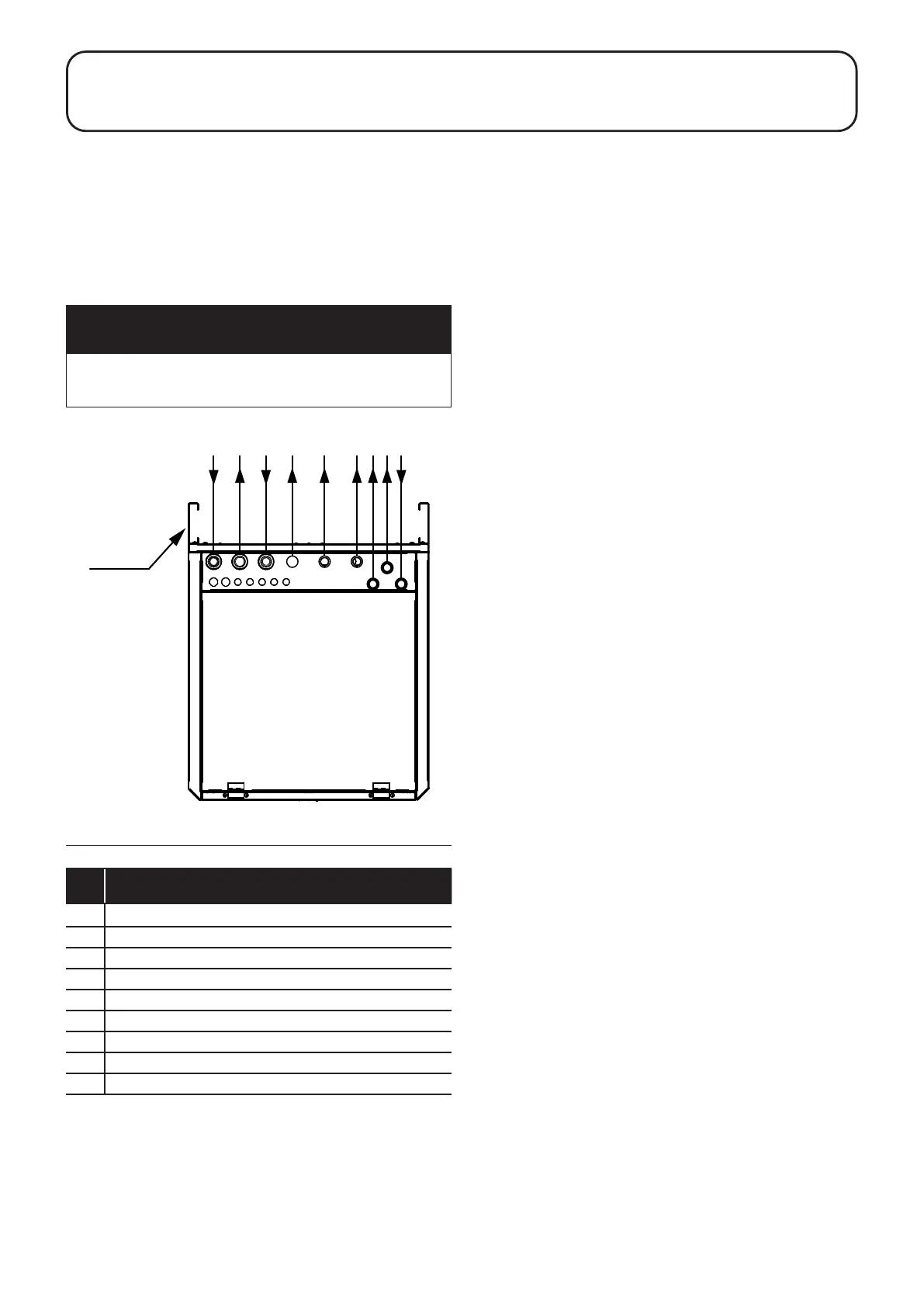
Table 3-1: Key to Figure 3-1
Item Description
A 28mm Return from heating circuits
B 28mm Return to heat pump
C 28mm Flow from heat pump
D 22mm Flow to heating zone 3 (pipe blanked)
E 22mm Flow to heating zone 2
F 22mm Flow to heating zone 1
G 22mm DHW outlet
H 22mm Balanced cold outlet
I 22mm Cold mains inlet
Figure 3-1: Cylinder connections
A B C E F G H I
D
100mm
spacer
channel
3.2 PRIMARY CONNECTIONS
Grant QR integrated indirect heat pump cylinders are factory
tted with primary circuit pipework that includes the following
components:
• 1 x 2-port zone valve for indirect hot water coil
• 2 x 2-port zones valves for heating (for two separate heating
zones)
• 1 x Blanked pipe tail for a third heating zone if required
• 1 x Digital dual thermostat (Cylinder thermostat and High
Limit thermostat)
• 1 x 18 litre primary circuit expansion vessel
• 1 x 22mm automatic system bypass with ow setter (refer to
Section 3.6)
• 1 x Approved lling loop to ll the primary circuit
• 1 x Primary circuit pressure gauge
• 1 x Fill & ush valve (refer to Section 3.7)
3.2.1 MAKING THE PRIMARY CONNECTIONS
Make the primary circuit and heat pump connections to the
cylinder as follows (refer to Figure 3-1):
1. Remove the disposable pipework transit cover from the top
rear of the cylinder by removing the three screws at the top of
the rear panel of the cylinder.
2. If the 100mm spacers supplied with the cylinder (see Figure
3-1) are to be tted, t them before manoeuvring the cylinder
into its nal position. To do this:
• Remove the two screws supplied in the cylinder
accessories pack.
• Loosely t one of the screws supplied in the accessories
pack into the top threaded hole on one of the sides of
the rear panel of the cylinder.
• Slacken o the three screws below the screw tted in
the above step.
• Take one of the 100mm spacers supplied with the
cylinder, ensuring it is orientated correctly (i.e. with
the at side facing outwards) and hang it on the four
loosened screws. When the spacer is in position, tighten
the four screws.
• Repeat the above steps to t the remaining 100mm
spacer.
• These spacers provide a space behind the cylinder to
run pipework.
3. Manoeuvre the cylinder/cabinet into its nal position.
4. The primary ow connection from the heat pump should be
made to cylinder connection C (refer to Figure 3-1 and Table
3-1). To do this:
• Remove one of the 28mm straight compression couplers
from the accessories pack supplied with the cylinder and
make the connection to primary circuit connection C of
the cylinder (see Figure 3-1).
• Primary circuit connection C of the cylinder can now be
connected to the 28mm ow pipe from the heat pump.
5. The primary return connection to the heat pump should be
made to cylinder connection B (refer to Figure 3-1 and Table
3-1). To do this:
• Remove one of the 28mm straight compression couplers
from the accessories pack supplied with the cylinder and
make the connection to primary circuit connection B of
the cylinder (see Figure 3-1).
• Primary circuit connection B of the cylinder can now be
connected to the 28mm return pipe to the heat pump.
6. The primary ow to heating zone 1 should be made to
cylinder connection F (refer to Figure 3-1 and Table 3-1).
To do this:
• Remove one of the 22mm straight compression couplers
from the accessories pack supplied with the cylinder and
make the connection to primary circuit connection F of
the cylinder (see Figure 3-1).
• Primary circuit connection F of the cylinder can now be
connected to the 22mm ow pipe to heating zone 1.