Page 33
APPENDIX A DIGITAL DUAL THERMOSTAT
A.1 GENERAL INFORMATION
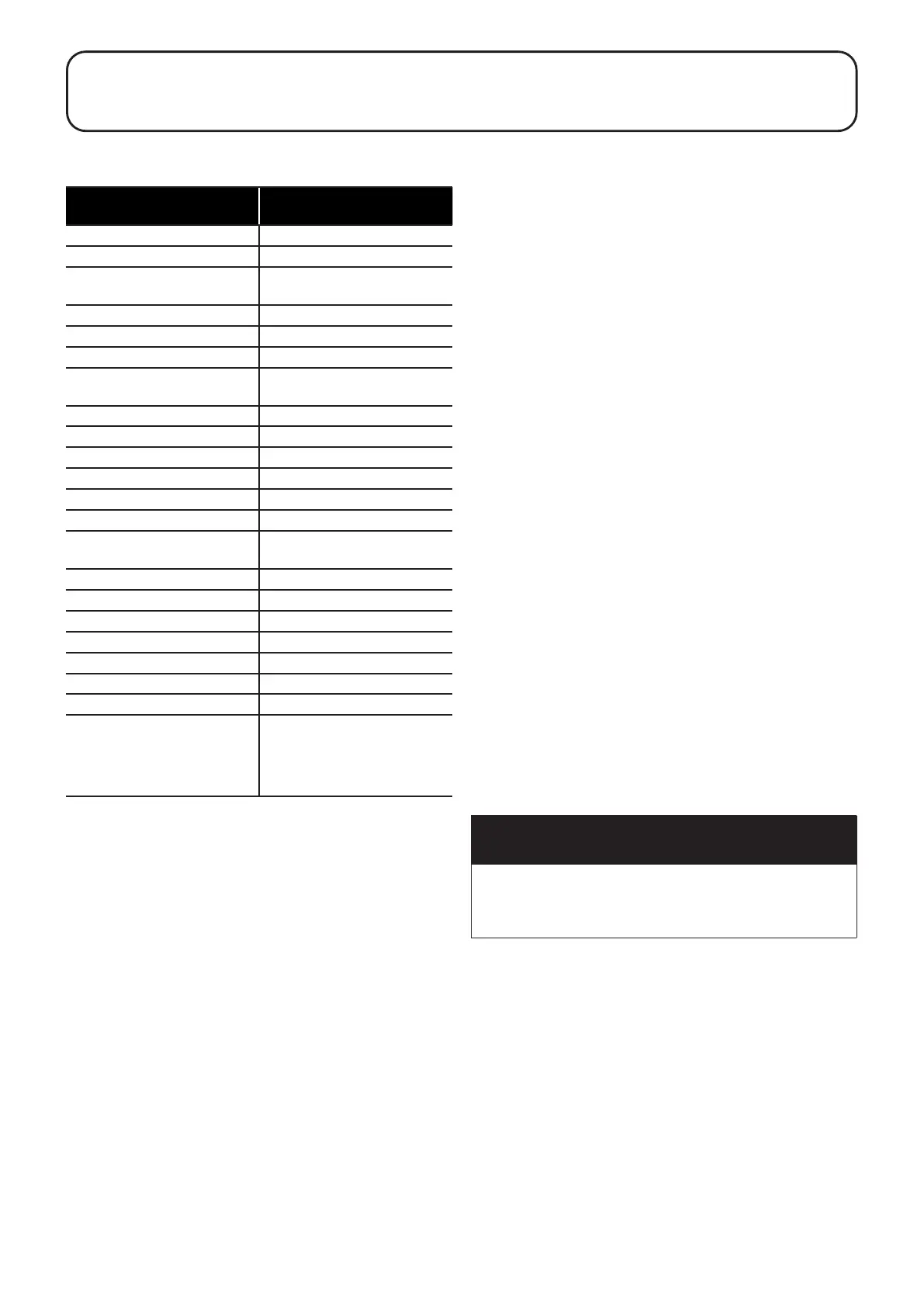
A.1.1 THERMOSTAT SPECIFICATION
Make and model
Selco Industry -
TW04E9B000D100
Adjustable temperature range 25 - 65°C ± 1°C
Temperature dierential ∆t 4°C ± 1°C
Limiter thermostat operating
temperature
80.0°C +0 / -3°C >> manual reset
push button
Failsafe function INCLUDED
Temperature rate of change Any - no limitation
Restart delay to prevent short
cycles
3 minutes
Frost protection ∆t 4°C ± 1°C
Power supply/power consumption 240V AC ± 10%
Output contacts rating SPDT C-1 8A @ 250V AC
Output contacts rating SPDT C-2 2A @ 250V AC
Dierential after manual reset 20°C +3 / -0°C
Sensor NTC / range work 20K ± 3% B25-85 = 3977K ± 1%
-20°C .. +115°C
Electrical rigidity 4000 V AC
Insulation resistance 50MΩ @ 500V DC
Degree of protection sensor IP65
Max head temperature 60°C
Max bulb temperature 120°C
Degree of protection IP40
Reference standard EN 60730-1, EN60730-2-9
EU Directives: 2014/35/EU - CE -
EMC 2014/30/EU
Reach and RoHS conforms
A.1.2 FAIL SAFE FUNCTION
The "Fail Safe" function will operate if:
• The overheat protection function operates (refer to Section
A.1.3).
• The contents of the cylinder drops to a temperature of -28°C.
• The temperature probe is disconnected from or incorrectly
connected to the thermostat (refer to Section A.1.4).
You will be able to tell if the Fail Safe function has operated, as
the warning triangle in the bottom left hand corner of the display
screen will be illuminated and the indicator LED will be illuminated
red (see Figure A-1).
To reset the digital thermostat and return it to normal operation
after the Fail Safe function has operated:
1. Gently pull on the temperature dial to uncover the manual
reset button, refer to Figure A-2.
2. Push the manual reset button and replace the temperature
dial.
3. Turn the temperature dial to set the desired temperature
(recommended to be 60°C).
4. Switch the thermostat o at the mains supply and back on
again.
A.1.3 OVERHEAT PROTECTION FUNCTION
The thermostat is equipped with an overheat protection function,
which is designed to operate if the contents of the cylinder
reaches a temperature of 80°C.
If this function operates, the thermostat must be manually reset in
order to resume operation. To do this:
1. Allow the temperature of the contents of the cylinder to drop
below 65°C. This temperature is indicated on the thermostat
display, refer to Figure A-1.
2. Investigate the cause of the overheat situation and rectify any
faults.
3. Follow steps 1-4 outlined in Section A.1.2.
It is possible that this function may operate during transport or
while the unit is being manoeuvred into position. If this is the case
please follow the above procedure to reset the thermostat.
If this function operates, the warning triangle in the bottom left
hand corner of the display screen will be illuminated and the
indicator LED will be ashing red (see Figure A-1).
A.1.4 TEMPERATURE PROBE NOT
RECOGNISED
If the temperature probe is either not connected or incorrectly
connected, the thermostat's "Fail Safe" function will be activated,
refer to Section A.1.2 for further details.
If this eventuality occurs, to rectify:
1. Ensure the mains power supply to the thermostat is switched
OFF.
2. Remove the two screws securing the wiring cover to the back
of the thermostat (see Figure A-1) and carefully remove the
wiring cover.
3. Ensure that the temperature sensor is correctly connected to
the thermostat. Refer to Figure A-3 for temperature sensor
wiring details.
4. Replace the wiring cover on the back of the thermostat,
ensuring the temperature probe is routed through the hole
in the centre of the cover. Secure it with both screws, taking
care not to over-tighten the screws.
5. Reconnect the electrical supply to the thermostat
6. Follow steps 1-4 outlined in Section A.1.2.
7. Check for correct operation.
! WARNING !
Ensure the electrical supply to the thermostat has been
isolated before removing the wiring cover.
Ensure the wiring cover has been replaced before
reconnecting the electrical supply to the thermostat.
A.1.5 DISPLAY SCREEN
During normal operation, the display screen will show the
temperature of the contents of the cylinder.
When the temperature of the contents of the hot water cylinder is
below the target temperature set by the thermostat, a small ame
icon will appear in the top left hand corner of the display screen
approximately 10 seconds after the status of the indicator LED
changes. See Figure A-1.
If the "Fail Safe" function operates (refer to Section A.1.2), a
warning triangle will appear in the bottom left hand corner of the
display screen approximately 10 seconds after the status of the
indicator LED changes. See Figure A-1.
Appendix A: Digital Dual Thermostat