Section 2: Technical DataPage 8
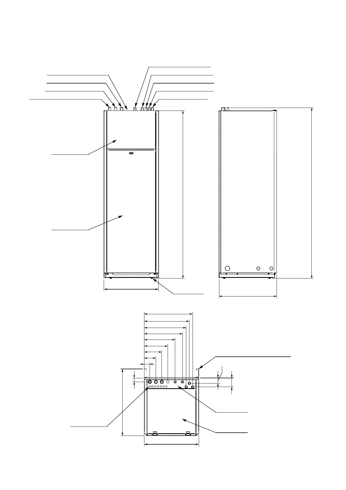
Figure 2-1: Grant QR integrated indirect heat pump cylinder dimensions
2.3 DIMENSIONS
Scale: NTS
Paper Size: A3
Project Title: Grant UK Integrated Cylinder Dimensions
Drawing Set: Integrated Cylinder
Status: Sent for approval
Rev Date: 12/10/21
Drawn By: CG
Checked By:
Dwg. No. IC0001
Revision: 0.1
This drawing and its content is subject to copyright. Use other than for its original intended purpose must be arranged with an employee of Grant UK Ltd.
Hopton House, Hopton Industrial Estate, Devizes, Wiltshire, SN10 2EU, tel; 01380 736920
Notes: All dimensions given are in mm
unless expressed otherwise.
Revision Details:
0.1
13/10/21 Sent for approval
62
100mm spacers if required (supplied)
Adjustable feet
594
627
127
192
257
337
417
457
490
527
1821
57.5
97.5
1855
42.5
Return from heating circuits - 28mm
Return to heat pump - 28mm
Flow from heat pump - 28mm
Flow to heating zone 3 - 22mm
(optional, pipe blanked)
(pipe tail below top of cylinder)
Flow to heating zone 2 - 22mm
Flow to heating zone 1 - 22mm
Balanced cold outlet - 22mm
Cold mains inlet - 22mm
594
DHW outlet - 22mm
727
(Front view)
(Left side view)
(Top view)
Lower front panel
Upper front panel
Front top panel
Rear top panel
Cable entry points