Section 1: IntroductionPage 4
1.1 GENERAL
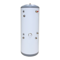
The Grant QR integrated indirect heat pump cylinder encloses a
Grant QR pre-plumbed 210 litre single coil cylinder within a white
casing with a footprint similar to that of a fridge.
Also enclosed within the casing are a number of factory tted
components that are required when installing a sealed central
heating system and unvented hot water system.
Refer to Section 1.6 for a list of these components.
The ergonomic design of this cylinder makes it suitable for
installation in a kitchen or utility room, when a separate airing
cupboard or plant room is not available.
1.2 INSTALLATION REQUIREMENTS
Thank you for purchasing a Grant unvented hot water storage
cylinder from our QR range.
These Installation and User instructions must be read carefully
before you begin installing the cylinder.
The cylinder must be installed by a competent person in
compliance with all current legislation, codes of practice and
local by-laws covering the installation of an unvented hot water
cylinder.
Please also make sure that the installation complies with the
information contained in these Installation and User Instructions.
To prevent damage to the coil, cylinder and cylinder connections,
make any soldered joints before connecting pipework to the
cylinder.
1.3 WATER SUPPLY REQUIREMENTS
We recommend that your Grant unvented cylinder is installed with
an uninterrupted water supply.
Where possible, the unit should be fed via a Ø22 mm supply pipe.
It requires a supply pressure of at least 1.5 bar with a ow rate of
at least 25 litres per minute as a minimum for it to function.
Even with this pressure and ow rate, the ow from the outlets
will be disappointing if several outlets are used simultaneously.
Generally speaking, the higher the supply pressure, the better the
system will function.
The cylinder control equipment is factory set to limit the incoming
system operating pressure to 3 bar. The maximum supply
pressure into the pressure reducing valve (PRV) is 12 bar.
1.4 LOCATION
The unit is designed to be oor standing, vertically mounted,
internally in a frost-free environment. When choosing a suitable
location for the cylinder, consideration should be given to the
routing of the discharge pipe to a convenient point and also
the availability of an adequate power supply for connecting the
immersion heater.
The cylinder may stand on any at and level surface without any
special foundation requirements, provided that it is suciently
robust to support the full weight of the cylinder (refer to Section
2.1).
The cylinder is provided with adjustable feet to help level the
cylinder. The feet can be adjusted using the special tool supplied
with the accessories kit.
The position of the cylinder should be such that easy access is
provided for servicing the controls and replacing the immersion
heater should the need arise.
Generally, pipe runs should be made as short as possible and
lagged to prevent heat loss.
1.5 STORAGE AND HANDLING
If the cylinder is not being installed immediately, it should remain
in its carton to prevent damage. We recommend that the cylinder
be transported to its installation position on a sack truck or similar
whilst still within the carton.
! CAUTION !
Do not use the Temperature and Pressure relief valve (T&P
relief valve) as a handle when moving and positioning the
cylinder.
With pre-plumbed cylinders, do not use the pipework as a
carrying handle when lifting, moving and positioning the
cylinder.
1.6 ABOUT YOUR CYLINDER
Grant QR integrated indirect heat pump cylinders are factory-tted
with the following components:
Primary circuit pipework
• 1 x 22mm 2-port zone valve for hot water
• 2 x 22mm 2-port zone valves for heating (for two separate
heating zones)
• 1 x blanked additional heating zone ow pipe
• 1 x 22mm automatic by-pass
• 1 x 15mm approved lling loop
• 1 x 19 litre expansion vessel
Cold water inlet pipework
• 1 x Cold water inlet manifold
• 1 x Temperature and pressure relief valve
• 1 x 15-22mm Tundish
• 1 x Drain cock
• 1 x 19 litre potable water expansion vessel
Electrical
• 1 x Grant EP001 Wiring Centre (pre-wired to the zone valves
and dual thermostat). Refer to Grant UK DOC 0176 for more
detailed information.
• 1 x 3kW electric immersion heater
• 1 x Greenbrook T205-C timer (for immersion heater)
• 1 x Dual thermostat (cylinder thermostat and high limit
thermostat)
• 5 x M16 cable glands
• 2 x M20 cable glands
Grant QR integrated indirect heat pump cylinders have a single
coil designed for connection to an air source heat pump, such as
the Grant Aerona³ range. If another heat source, such as a boiler
or another make of heat pump is to be connected, please refer to
the manufacturer’s installation instructions for more information.
The coil must be connected using a 2-port motorised valve
(factory tted) to shut o the ow from the primary source and
electronically interlocked with the heat source via the cylinder
control and high limit thermostat.
Information on the electrical wiring of this 2-port motorised valve is
given in Section 5 of these instructions.
Please refer to Figure 2-2 for positions of the components tted to
these cylinders.
1.7 PRIMARY CIRCUIT PIPEWORK
CONNECTIONS
All primary circuit pipework connections to the cylinder MUST be
made in accordance with Figure 3-1. Refer to Section 3 (Primary
Circuit Installation).
1 INTRODUCTION

 Loading...