11
Grant Vortex External Module
4 - GENERAL BOILER INFORMATION
4 A metal bowl type filter with a replaceable
micronic filter must be fitted in the fuel supply line
adjacent to the boiler. A shut-off valve should be
fitted before the filter, to allow the filter to be
serviced.
5 A flexible fuel hose, adaptor and
1
/
4
" BSP isolation
valve are supplied loose with the boiler for the final
connection to the burner. If a two pipe system or
'Tiger Loop' type de-aerator is used, an additional
flexible fuel hose (600 mm) and
3
/
8
" to
1
/
4
" BSP male
adaptor are available to purchase from your local
stockist. If a 'Tiger Loop' is fitted it should not be
fitted indoors or within a boiler casing.
6 Metal braided flexible hoses should be replaced
annually when the boiler is serviced. Long life
flexible hoses should be inspected annually and
replaced at least every 60 months.
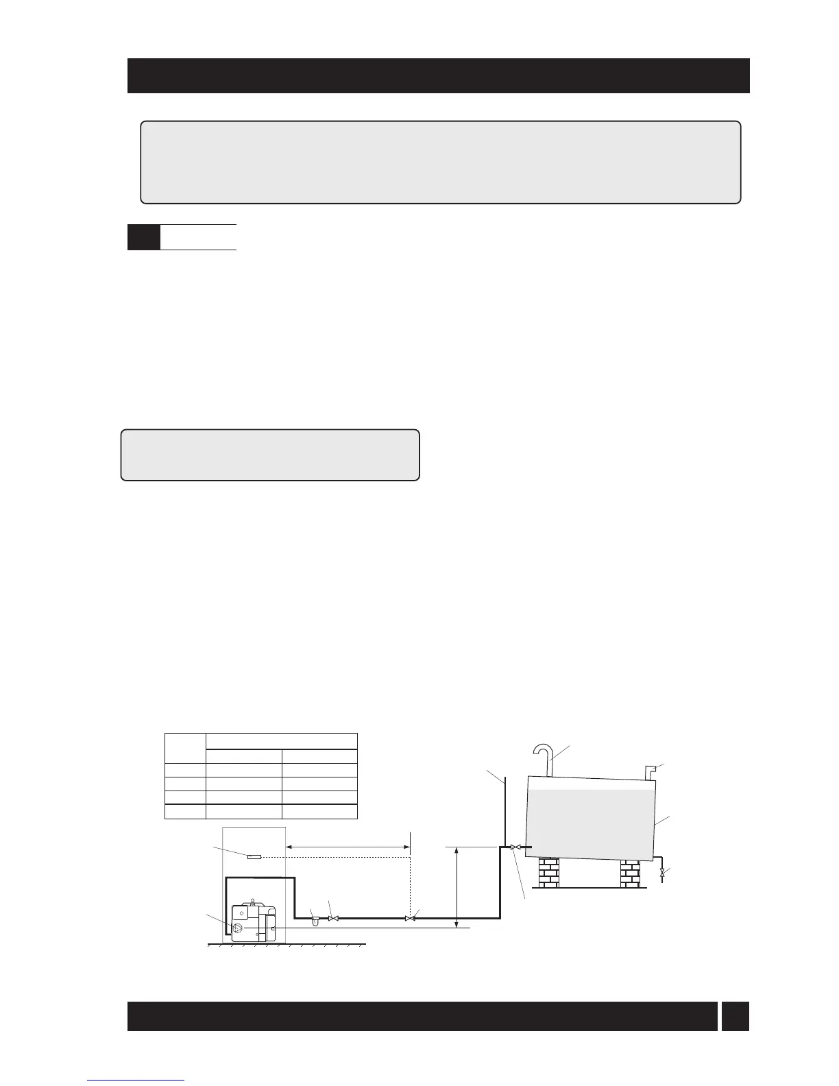
4.4.3 Single pipe system - (See Fig. 2)
1 Where the storage tank outlet is above the burner
the single pipe system should be used. The height
of the tank above the burner limits the length of
pipe run from the tank to the burner.
2 As supplied the burner is suitable for a single pipe
system.
4.4.1 Fuel storage
The tank should be positioned in accordance with the
recommendations given in BS 5410:1:1997, which gives
details of filling, maintenance and protection from fire.
A steel tank may be used and must be constructed to
BS 799:5:1987 and OFST 200.
A galvanised tank must not be used.
A plastic tank may be used and must comply with
OFST 100.
Note: Plastic tanks should be adequately and
uniformly supported on a smooth level surface, across
their entire base area.
4.4.2 Fuel pipes
1 Fuel supply pipes should be of copper tubing with
an external diameter of at least 10 mm.
Galvanised pipe must not be used.
All pipe connections should preferably use flared
fittings. Soldered connections must not be used on
oil pipes.
2 Flexible hoses must not be used outside the boiler case.
3 A remote sensing fire valve (not a fusible head type)
must be installed in the fuel supply line, with the
sensing head located above the burner.
Recommendations are given in BS 5410:1:1997.
Fuel supply
4.4
Regional statutory requirements may deem this appliance to be a 'controlled service'.
Where this is the case, it is a legal requirement that the appliance is installed and
commissioned either under the remit of building control or by a 'Competent person' such
as a suitably qualified Oftec registered technician.
Fig. 2 - Single pipe system
Filter
Fire
valve
Shut-off
valve
Shut-off
valve
A
Sludge
valve
Fill
pipe
Vent
pipe
Level
gauge
Fuel
storage
tank
Head A
(m)
Maximum pipe run (m)
0.5
1.0
1.5
2.0
10 mm OD pipe
10
20
40
60
12 mm 0D pipe
20
40
80
100
Fire
valve
sensor
Pump
1m