12
Grant Vortex External Module
4.4.5 Tiger Loop system - (See Figs. 4 and 5)
1 When the storage tank is below the burner, an
alternative to a two pipe system can be achieved
using the 'Tiger Loop' type oil deaerator. This
effectively removes the air from the oil supply on a
single pipe lift.
2 The de-aerator is connected close to the boiler as a
two pipe system (omitting the non-return valve) as
shown in Fig. 4. Refer to the manufacturers
instructions supplied with the de-aerator.
The de-aerator must be mounted vertically and
externally.
3 To be used with a de-aerator, the burner must be
fitted with an additional flexible fuel hose (a flexible
fuel hose (600 mm) and
3
/
8
" to
1
/
4
" BSP male adaptor
are available to purchase from your local stockist. See
Section 4.4.6.
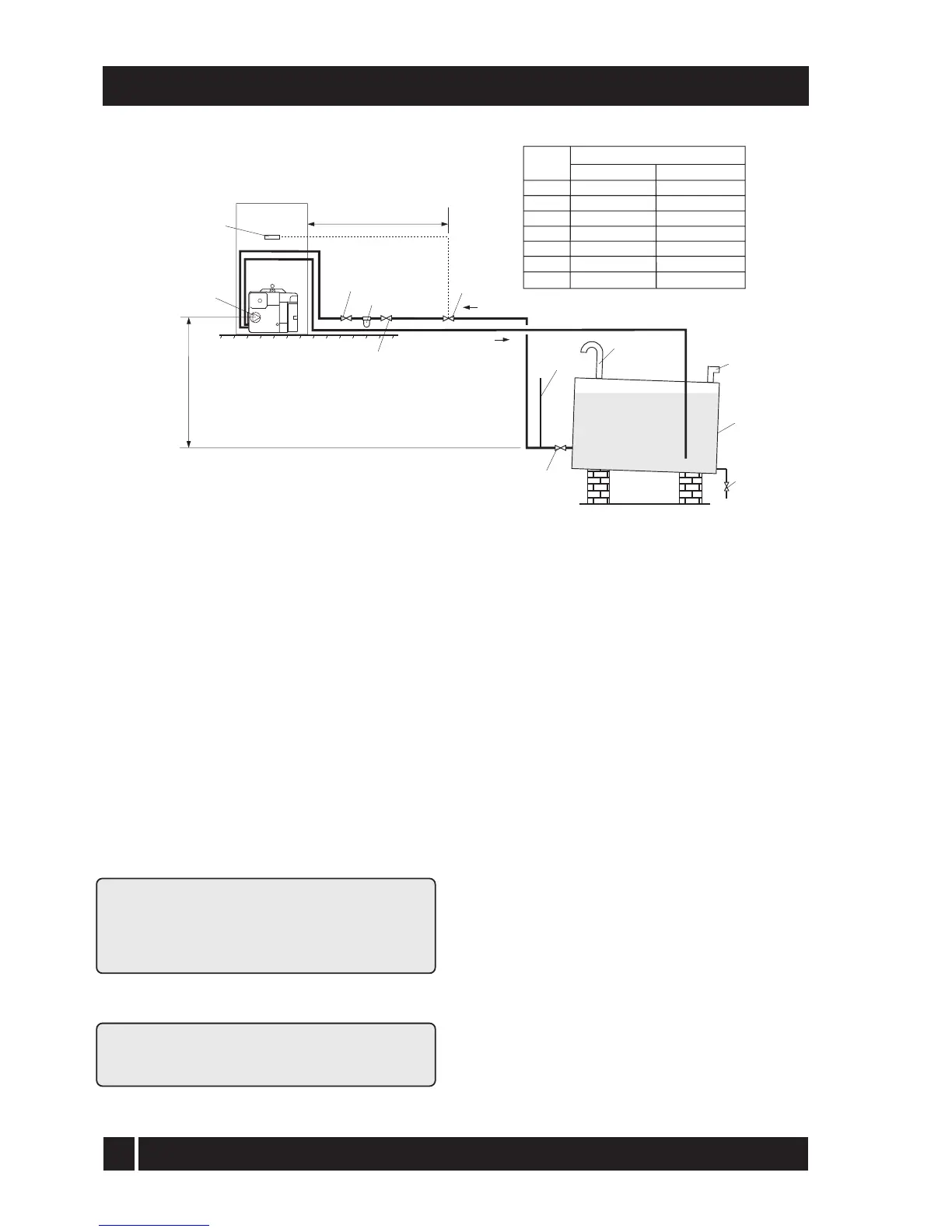
4.4.4 Two pipe system - (See Fig. 3)
1 When the storage tank outlet is below the burner,
the two pipe system should be used. The pipe runs
should be as shown in Fig. 3. The return pipe
should be at the same level in the tank as the
supply pipe, both being 75 to 100 mm above the
base of the tank. The pipe ends should be a
sufficient distance apart so as to prevent any
sediment disturbed by the return entering the
supply pipe.
2 Avoid the bottom of the tank being more than 3 m
below the burner.
3 A non-return valve should be fitted in the supply
pipe together with the filter and fire valve. A non-
return valve should be fitted in the return pipe if
the top of the tank is above the burner.
4 To be used with a two-pipe system, the burner
must be fitted with an additional flexible fuel hose
(a flexible fuel hose (600 mm) and
3
/
8
" to
1
/
4
" BSP
male adaptor are available to purchase from your
local stockist.
5 The pump vacuum should not exceed 0.4 bar.
Beyond this limit gas is released from the oil.
For guidance on installation of top outlet fuel tanks and
suction oil supply sizing, see OFTEC booklet T1/139.
Available at www.oftec.org.uk
4 - GENERAL BOILER INFORMATION
Fig. 3 - Two pipe system
Filter
Fire
valve
Shut-off
valve
Shut-off
valve
See
section 4.4.6
A
Return
Supply
Head A
(m)
Maximum pipe run (m)
0
0.5
1.0
1.5
2.0
3.0
3.5
10 mm OD pipe
35
30
25
20
15
8
6
12 mm OD pipe
100
100
100
90
70
30
20
Non
return
valve
Fire
valve
sensor
Sludge
valve
Fill
pipe
Vent
pipe
Level
gauge
Fuel
storage
tank
1m