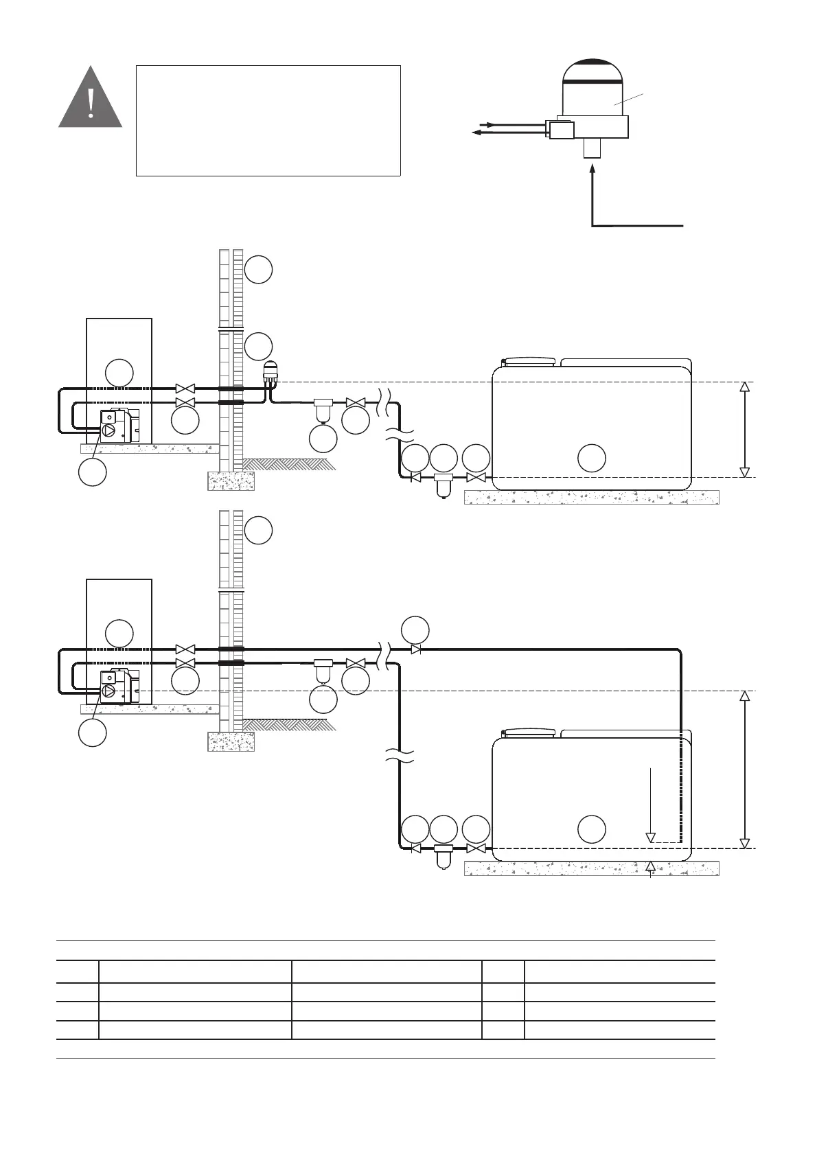
Number / item correspondence table diagrams fig 3-2/3-3
1 oil tank exterior wall 7 burner
2 isolation valve oil filter (max filtration 15μm) 8 non-return valve
3 oil strainer oil pump 9 air separator
10 boiler isolation valves
* Position of de-aeration device must be level with or above the oil pump
* The air separator must be positioned at the level of the oil pump or placed above
Figure 3-2: Bitube oil supply
Figure 3-3: Supply with oil fi lter pot fitted with TOC DUO air separator
123
2
4
4
5
8
8
5
9
7
7
6
6
10
10
3.5m Max
123
2
3.5m Max
150mm
10
Fuel Storage and Fuel SystemPage 14
1/4" BSP female
connections
Tiger Loop
SUPPLY
TO PUMP
RETURN
FROM PUMP
SUPPLY
FROM TANK
Figure 3-4: Tiger loop de-aeration device
Refer to your oil tank supplier for any advice
concerning the type of single-tube, two-tube
oil supply, fi lter pot with separator, piping
diameter, safety device, compliance with
safety standards. Grant IRL cannot be held
responsible for liability for a faulty fuel oil
supply.
CAUTION