22
• Unplug wires from clutch and remove center
bolt (item 18). Slide clutch off engine crank-
shaft.
• Reverse order to install new clutch.
• Torque clutch bolt to 50 ft lbs. Run clutch 15
minutes, then torque to 50 ft lbs again.
CLUTCH / BRAKE BURNISHING
A new clutch, or one that has not been
used for three months, will require
burnishing to dress drive surfaces.
The clutch could fail if you do not
accomplish the following procedure.
Place tractor in neutral and start engine. Turn
clutch switch on 30 seconds and off 30 seconds,
five times at half-throttle and repeat five times at
full throttle. The time interval allows the clutch
surface to cool.
ENGINE TROUBLESHOOTING
Should you experience trouble in starting the engine,
use the following guide to locate possible causes.
Engine will not crank:
• Battery is discharged.
• Blown starter fuse.
• PTO switch is “ON”.
• Steering levers are not out in neutral.
• Steering lever switches are out of adjustment
(listen for the switch “click”).
• A loose wire or connection.
Engine cranks, but will not start:
• Fuel tank is empty.
• Restricted fuel line or fuel filter.
• Blown ignition fuse.
• A loose wire or connection.
If the above points do not locate the problem, con-
tact your authorized Grasshopper dealer for repair.
Engine dies when steering levers are engaged:
• If engine starts and runs but dies when either
steering lever is engaged, check the follow-
ing. Make sure the parking brake is released.
The steering levers cannot be engaged with
the parking brake on. With the key switch
“ON” and the seat switch engaged, check for
ground at the two yellow wires on the seat
switch. If there is ground at one wire but not
the other, either the seat switch is defective or
it is not being activated properly.
• If there is ground at both yellow wires on the
seat switch, check for ground at the yellow
wire on the parking brake switch. If there is
no ground, the wire between the seat switch
and the parking brake switch is broken. If
there is ground at the yellow wire, check for
ground at the white wire. If there is no
ground at the white wire, the parking brake
switch is defective and must be replaced.
NOTE: These tests must be performed with an
accurate voltmeter. Do not use a test light; the
amperage in this circuit is too low to light a test
light properly. This circuit is the ground side of
relay A.
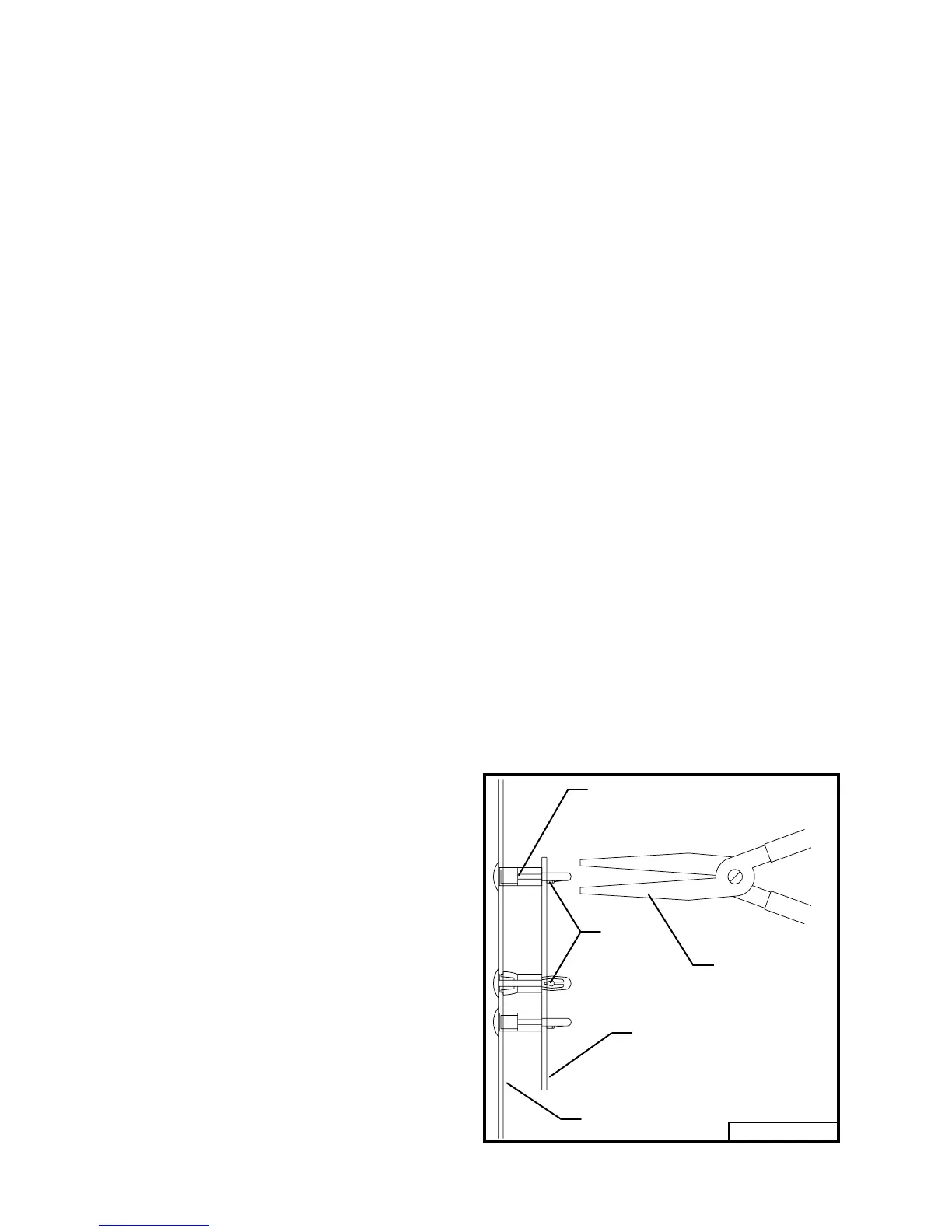
WIRING CIRCUIT BOARD REMOVAL
Remove the circuit board from the console by com-
pressing the keeper in each of the three circuit board
support spacers with needle nose pliers (refer to
Fig. 7). Slide the board past each keeper when it is
compressed.
Fig. 7
Keeper
Spacer - Circuit Board Support
Part no. 423690
Needle Nose
Pliers
Console Side
95040
Circuit Board
IMPORTANT