21
ADJUSTMENTS AND TROUBLESHOOTING
Never make adjustments with the
engine running.
LOSS OF POWER IN THE DRIVE
SYSTEM
Check the fluid level and be sure the proper amount
of fluid is in the expansion tank. The cooling
fins and fan blades should be clean and free of
foreign matter.
NO POSITIVE NEUTRAL POSITION
If drive wheels travel forward or backward when
the steering lever is in swing-out position (neu-
tral), adjustment is required.
NEUTRAL ADJUSTMENT
(Refer to illustration page 31)
1. Block up under tractor frame so both drive
wheels are off the ground.
2. Make sure parking brake is released.
3. Remove linkage rod (item 28 or 29) from
transmission control arm (item 17).
4. Place steering levers in the neutral swing-out
position and start engine.
5. If either of the drive wheels turn, proceed
with the following adjustment.
6. Loosen locking nut (item 20) and rotate
pivot bolt (item 18) until neutral is achieved.
Tighten locking nut.
NOTE: Pivot bolt roller is mounted off center
and works as an eccentric when the bolt is
turned.
7. Repeat procedure for other side transmission.
8. Reinstall linkage rod in control arm. If ball
stud does not reinstall into control arm with-
out moving the control arm, adjust length of
linkage rod until it slides into control arm to
assure neutral adjustment will be maintained
when linkage is connected.
9. Test drive machine for straight line travel
with both levers full forward. If travel is not in
a straight line, adjust the steering lever
stop on the side that is the fastest i.e.: if ma-
chine goes to the left, adjust the right
steering stop to slow down the right trans-
mission until travel is straight ahead.
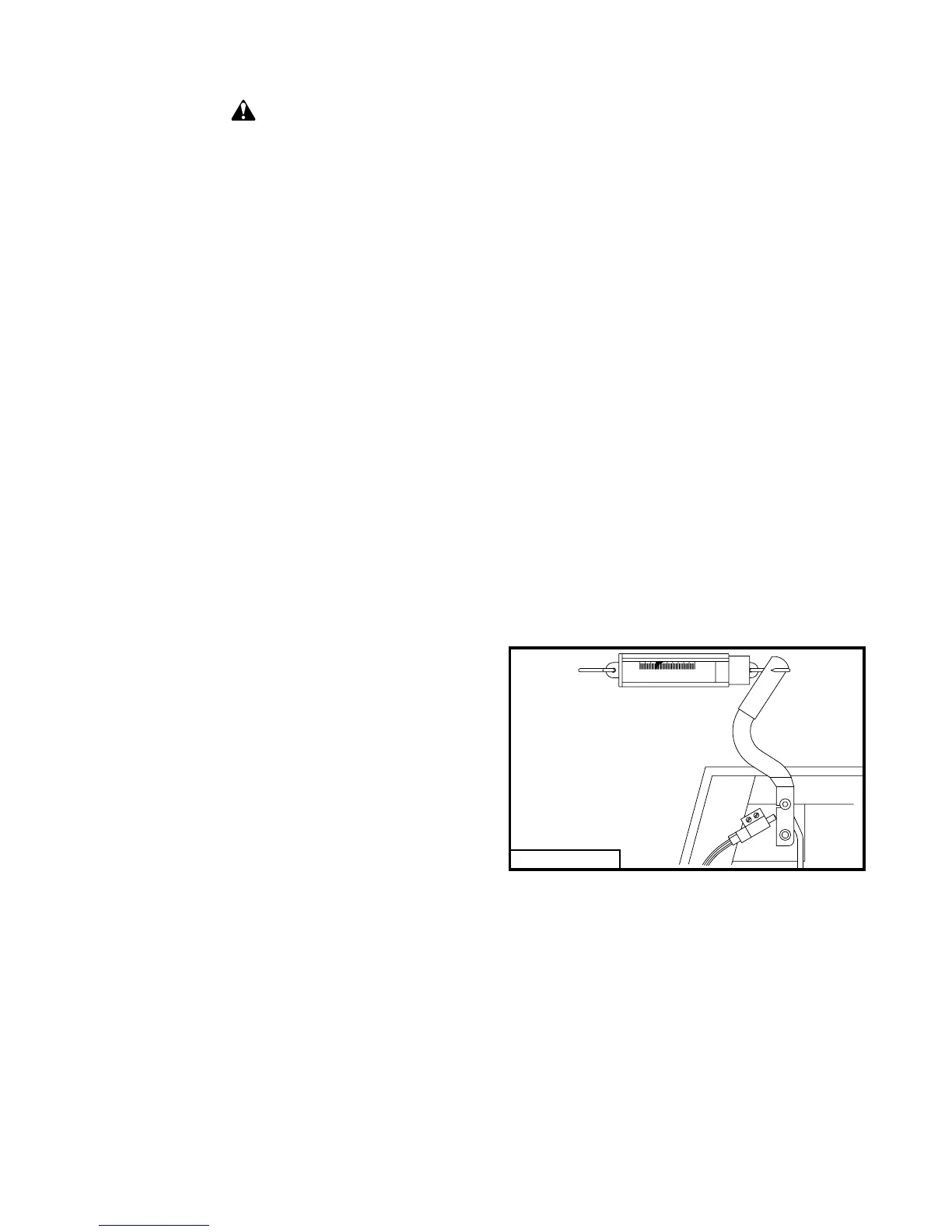
PARKING BRAKE ADJUSTMENT
(Refer to Fig. 6 and illustration on page 33)
Adjust the right and left brake individually. Discon-
nect the right brake linkage rod (item 25). Adjust
the linkage pin (item 27) to the left brake until it
takes 14 lbs of pull at the top of the hand lever to
apply the parking brake. Adjustment of brake link-
age rod (item 22) may also be required. Connect
the right brake linkage.
Disconnect the left brake linkage rod and adjust the
linkage pin attached to the right brake until it takes
14 lbs of pull at the top of the hand lever to apply the
parking brake. Connect the left brake linkage.
With both brakes connected it should take 28 lbs of
pull at the top of the hand lever to apply the parking
brake. Adjust the brake linkage rod (item 22) if
necessary.
CLUTCH REMOVAL /
REPLACEMENT
(Refer to page 27 or 29)
• Remove two carriage bolts (item 42). Lift out
weight cover and rear weights.
(Refer to page 36)
• Remove anti-rotation bracket (item 19).
• Using a 15/16 inch wrench, rotate the idler arm
(item 23) with idler pulley (item 30) away from
belts and remove drive belts (item 37).
CAUTION
Fig. 6
97069A
0
10
20
30
40 50