2.2. Binding“ multiple receivers in one model
If required, it is also possible to bind multiple receivers to the transmitter for a particular model. The rst
step is to bind each receiver individually using the procedure already described.
When the system is in use, the receiver which is switched on rst is the Master receiver. Any telemetry
sensors installed in the model must be connected to this unit, as only the Master receiver transmits
sensor data using the downlink channel. The second and all further receivers operate in parallel with the
Master receiver but in Slave mode, with the downlink channel switched off.
The control functions can also be distributed amongst multiple receivers; this is carried out using the
Channel Mapping function of the SMART-BOX (Order No. 33700). In the same way it is possible to as-
sign one control function to multiple receiver outputs; a typical example would be the use of two servos
for each aileron instead of only one, etc.
2.3. Fail-Safe function
In its default state (as delivered) the receiver is set to “Hold” mode, i.e. if a fail-safe situation occurs, all
the servos connected to it maintain the last position detected as valid. In this mode the green LED on
the receiver starts ashing when interference occurs, and the red LED on the transmitter goes out. The
transmitter also starts beeping about once per second as an audible warning.
You can exploit the safety potential of the fail-safe option by at least programming the throttle channel to
respond to a fail-safe situation: the throttle channel of an engine-powered model should be set to idle,
the throttle channel of an electric-powered model to “stop”, and the throttle channel of a model helicopter
to “Hold”. If interference should occur, these settings will help prevent the model ying out of control,
possibly causing personal injury or property damage.
Please refer to the appropriate section in your RC system instructions for the procedure.
Manual Receiver GR-12 Graupner HoTT 2.4 02
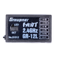
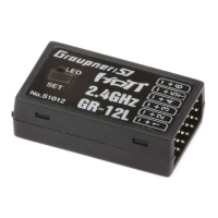
3. RECEIVER
3.1 Connections
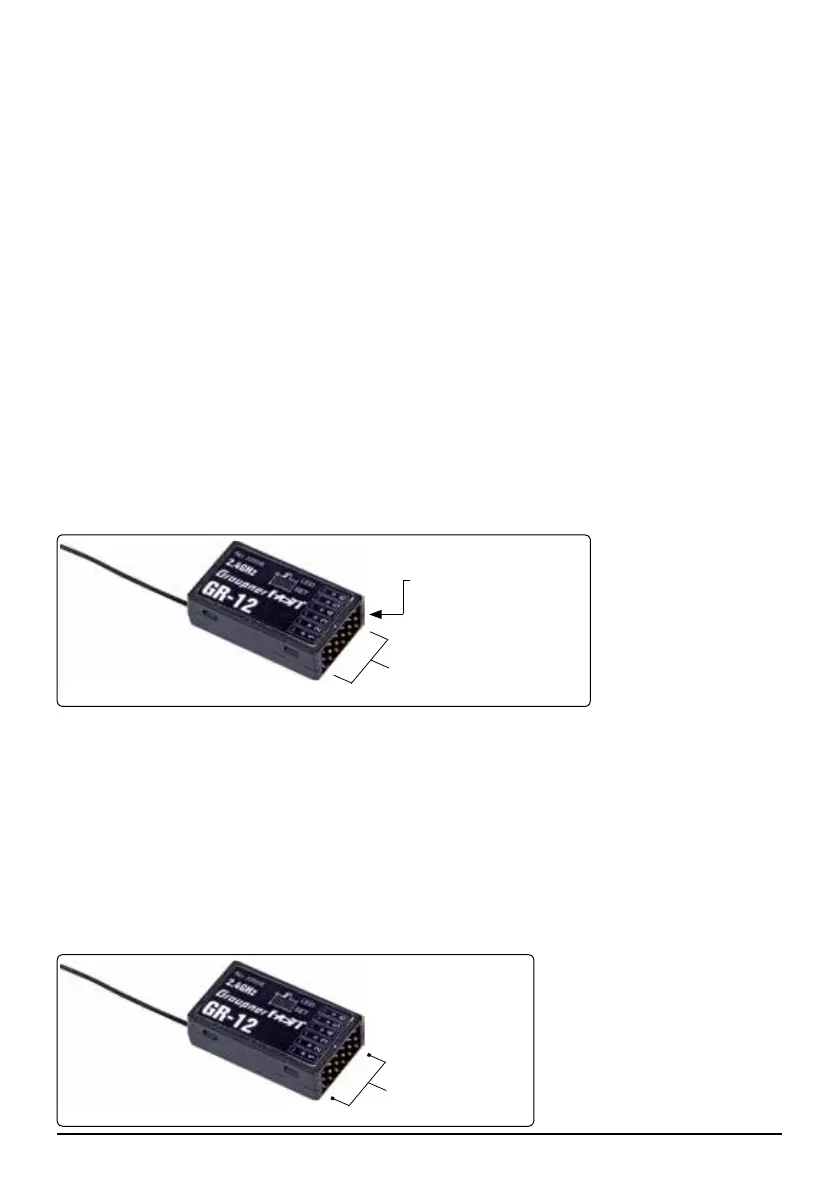
Plug the servos into the row of sockets on the right-hand end of the receiver. The connector system is
polarised; note the small chamfer on one edge. Never use force - the plugs should engage easily and
fully. The socket polarity is also marked on the case: brown wire (-), red (+) and orange (signal).
The servo sockets of the Graupner-HoTT 2.4 receiver are numbered. It is also possible to program
channel 6 for the sum signal using the SMART-BOX (Order No. 33700). This is important for certain
optional devices which require this signal.
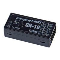
Power supply for receiver 33506
When using High Power servos, connect the receiver power supply/s preferably to the outer ports of the
receiver. If necessary, the servos can be connected to this sockets in parallel with the power supply; a
Y-lead (Order No. 3936.11) is required for this.
When using a dual power supply,
use the sockets on the outside:
Receiver 33506 (GR-12): Chan-
nel 1 and 6 (or 2 and 5)
Servo sockets
Telemetry socket
(channel 5)
Channel 1 and 6
 Loading...