4. FIRMWARE UPDATE GRAUPNER-HOTT 2.4 RECEIVER 33505 / 33506
Firmware updates for the transmitter RF module or receiver can be transferred via the DATA or telemetry
interface in conjunction with a PC running Windows XP, Vista or 7. For this you also require the USB
interface, Order No. 7168.6, and the adapter lead, Order No. 7168.6A or 7168.S, which are available
separately. When using the receiver GR-12S (Order No. 33505) the adapter cable Order No. 23048 is
also needed.
The programs and les required for this are available from www.graupner.de in the Download area for
the corresponding products.
Install the Firmware Update Utility Graupner and the USB drivers on your computer. Check the system
requirements!
Connect the adapter lead to the USB interface, Order No. 7168.6. This
socket is also polarised; note the small chamfer on one edge. Never use
force - the plug should engage easily and fully.
4.1. Receiver
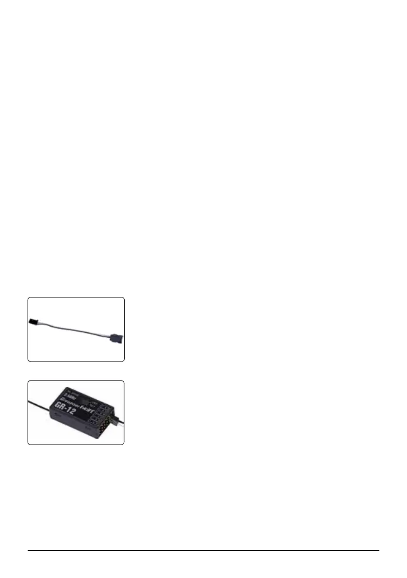
Receiver GR-12 (Order No. 33506):
Connect the adapter lead to the socket Channel 5 of the receiver, as
shown in the illustration. This socket is also polarised; note the small
chamfer on one edge. Never use force - the plug should engage easily
and fully.
The black wire (-) must be on top, the orange wire (T) down.
Receiver GR-12S (Order-No. 33505): the adapter cable Order No. 23048
is also needed.
4.2. Update procedure
Ensure that the adapter lead is congured as shown in the illustrations, and is connected correctly to
the transmitter or receiver.
Start the Graupner Firmware_Upgrade_grStudio.
Under ‚Port Select‘ select the correct COM port, i.e. the one to which the USB lead is connected - select
„Silicon Labs CP210x USB to UART Bridge“ and press „OK“.
Choose ‚Device‘ → ‚HoTT Receiver‘
Now click on the “File Browse” button and select the folder containing the previously loaded rmware le
ending in *.bin. If everything is correct, the le will appear in the corresponding window (A).
03 Manual Receiver GR-12 Graupner HoTT 2.4
The socket marked “5” - channel 5 - is intended for the optional telemetry sensors and is used for loading
rmware updates in conjunction with the USB interface. When using the receiver GR-12S (Order No.
33505) the adapter cable Order No. 23048 is also needed.
With telemetry sensors connected to socket 5, servos will not longer work at this output!
Note: to use the telemetry function of channel 5, select the telemetry menu SETTING AND DATA
VIEW of the transmitter or Smart-Box, go to the Display „RX CURVE“ and “5CH FUNCTION“ and
select „SENSOR“ instead of „SERVO“. With telemetry sensors connected to socket 5, servos will not
longer work at this output! As standard the servo function is enabled on channel 5 - „SERVO“ displayed.
3.2. Low voltage warning
If the receiver voltage falls below 3.8 V, the transmitter’s RF module generates a low voltage warning in
the form of a “general alarm sound”: a steady beeping at intervals of about one second.
3.3. Temperature warning
If the receiver temperature falls below -10° C or exceeds +70° C, the transmitter’s RF module generates
a temperature warning in the form of a “general alarm sound”: a steady beeping at intervals of about
one second.
 Loading...