14 / 24
33506_33508_33512_33516_T1V2sh
ശ SUMD
Digital sum signal of the control channel 04 to max. 16.
HD: Hold the last servo position in case of Fail-Safe
FS: Moving to the programmed positions in case of Fail-Safe
OF: (OFF) switch-off of the SUMD signal in case of Fail-Safe
ശ SUMD3
Digital sum signal adapted to the transmitter mz-32 HoTT for
the transmission of 32 control channels including their digital
switches.
ശ SBUS
Digital sum signal in SBUS format.
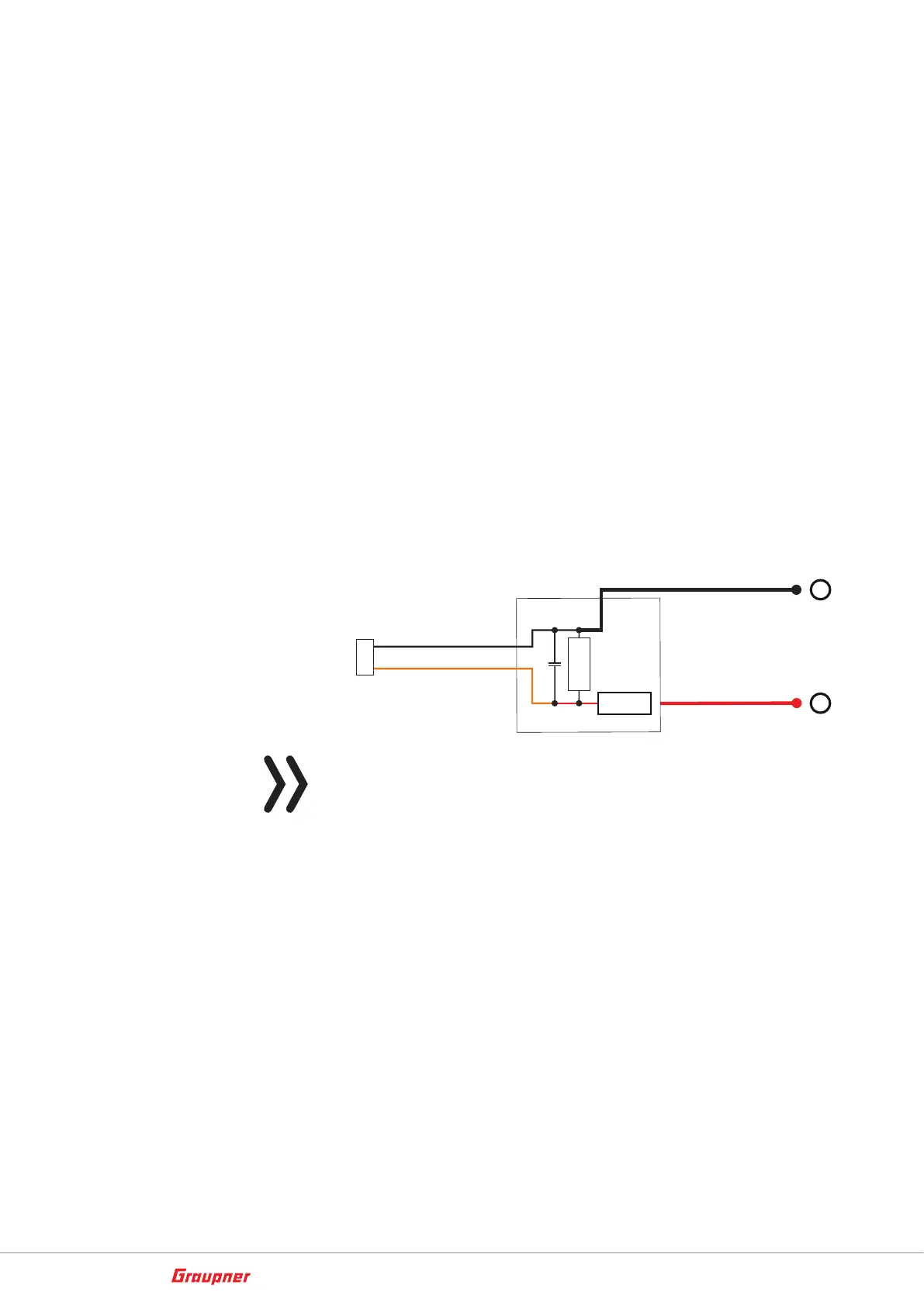
• BATT V
After switching as described before, a DC voltage off max. 25,5 V
can be displayed instead of the receiver voltage. This way it is
possible to monitor the main battery voltage without using exter-
nal sensors. The ESCs S3082 and S3083 have this switch already
included.
50 mm
100nF
2k7Ω
22kΩ
max. 25,5 V =
–
+
Attention
Never connect a power supply with an output voltage higher than
8,4 V directly to a connection port of the receiver! The receiver and
all connected devices would be immediately destroyed.