33700 SMART-BOX - Graupner HoTT 2.4 08
Servo travel (TRAVEL +/-): this function is used to adjust the maximum servo travel (control surface travel)
of the connected servo. The adjustment is available separately for each direction
Cycle time (PERIOD): at this point it is possible to defi ne the speed of the servos’ response to movements
of the transmitter controls. This adjustment applies to all channels.
Note: if you are using analogue servos, you must set a value of 20 msec. If you are using digital servos
exclusively, 10 msec should be selected.
RX FAIL SAFE < >
OUTPUT CH: 01
INPUT CH : 01
MODE : FAI SAFE
F.S.Pos. : 1500usec
DELAY : 0.75sec
FAIL SAFE ALL: SAVE
POSITION : 1400usec
INC + DEC
INC
DEC
ENTER
ESC
RX FAIL SAFE < >
OUTPUT CH: 01
INPUT CH : 01
MODE : FAI SAFE
F.S. Pos. : 1500usec
DELAY : 0.75sec
FAIL SAFE ALL: SAVE
POSITION : 1400usec
INC + DEC
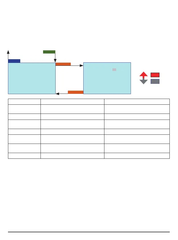
3.2.3 Failsafe Setup (RX FAIL SAFE)
To switch to the Failsafe setup display, press the ENTER button repeatedly until RX FAIL SAFE appears
on the screen.
Display Description Setup
OUTPUT CH Output channel select 1 – X, depends on the connected
receiver
INPUT CH Input channel select 1 – 16
MODE Fail-safe Mode Fail Safe / Hold / Off
Factory setting Hold
F.S. Pos. Failsafe Position 1000 - 2000 usec
DELAY Failsafe response time 0.25, 0.50, 0.75, 1.00sec
Factory setting 0.75 sec.
FAIL SAFE ALL Stores fail-safe positions for all control
channels
NO / SAVE
POSITION Failsafe position 1000 - 2000 usec
Output channel select (OUTPUT CH): this is where you select the desired channel; the remainder of the
fail-safe settings only affect the channel selected at this point.
Input channel select (INPUT CH): channel mapping function
The control functions can be distributed over several receivers in any sequence; alternatively multiple recei-
ver outputs can be assigned to the same control function. For example, this is useful if your aircraft features
two servos acting on each aileron instead of only one.
The SMART-BOX can be used to manage a maximum of sixteen transmitter channels. At this point you can
defi ne how the transmitter channels (INPUT) are assigned to the channels (OUTPUT) of the receiver(s).
If your model is fi tted with multiple receivers, the Master receiver is the last receiver to be bound. However,
in subsequent operations only the receiver which was bound last is able to make a telemetry connection
to the transmitter. On the other hand, this also means that only the last bound receiver can be addressed
using the Telemetry menu.