10 / 19
3974_MP_V3
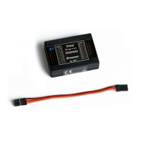
Setting the electric connections
The module consumes so little power that you can connect it directly
to the summed signal output (see receiver instructions) with the
included patch cable.
You can connect functions with low power consumption directly to
the switch channel of the module, but only if the total power con-
sumption of all the connected functions is lower than 1,0 A and only
if the receiver voltage is enough (see switch plan).
To allow an as universal as possible use of the module, the module
switches the ground (GND). This has the positive aspect that if nec-
essary each function can be powered by a different source.
To allow this it is important that the minus pole of each power source,
e.g. batteries, is connected to the other ones.
The functions will then be connected securely with the plus pole to
the related battery and the minus pole of the function will be con-
nected to the switch module.
In case of low currents the ground connection through the patch
cable of the receiver is enough, on the other hand if the current is
higher you should connect each ground separately (see switch plan).
Please note that inductive or capacitive functions ( as relais, motors
or capacitors, etc...) during the switch-on phase can require much
higher current than the one needed during the normal use. A tres-
passing of the limit values can damage the module.
 Loading...