12 / 19
3974_MP_V3
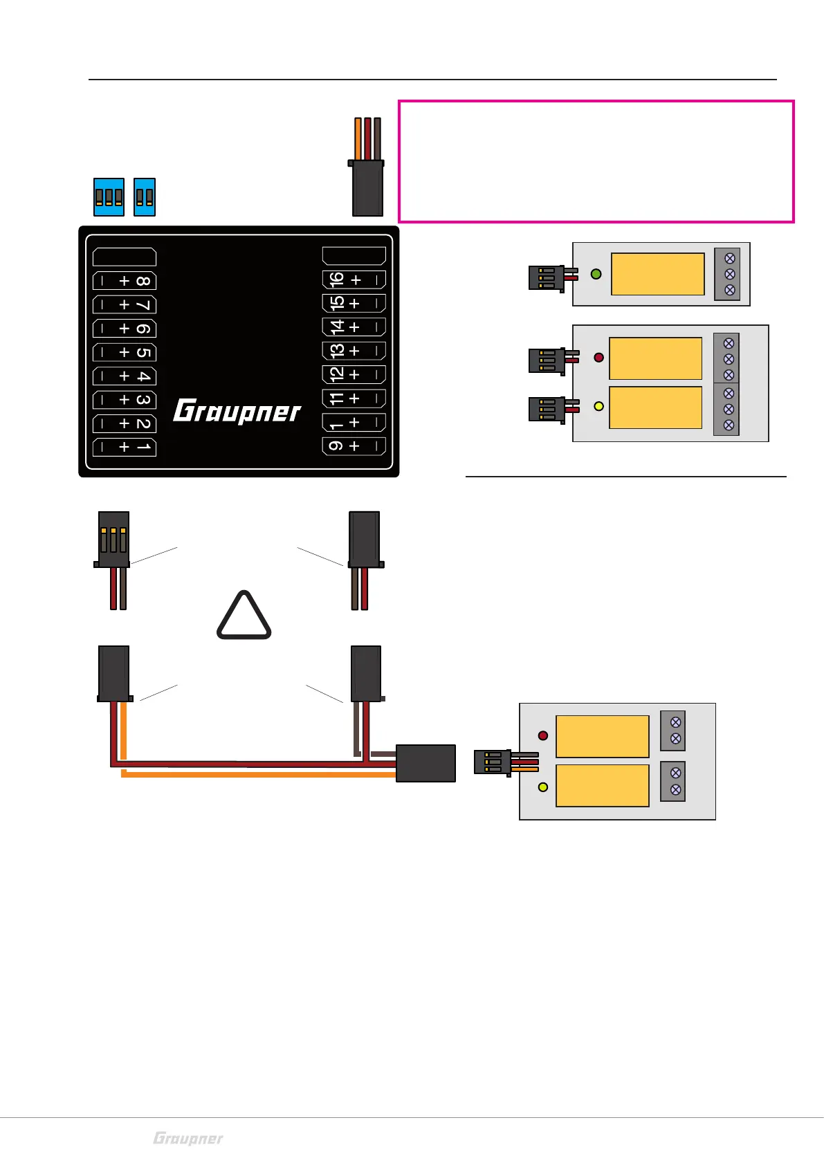
Connection diagram
Occupation of the pin lines:
X1 X2
Pin A B C Pin C B A
9 Jumper Jumper Jumper 18 FS pulse V+ GND
8 GND V+ Ch 8 17 Ch 16 V+ GND
7 GND V+ Ch 7 16 Ch 15 V+ GND
6 GND V+ Ch 6 15 Ch 14 V+ GND
5 GND V+ Ch 5 14 Ch 13 V+ GND
4 GND V+ Ch 4 13 Ch 12 V+ GND
3 GND V+ Ch 3 12 Ch 11 V+ GND
2 GND V+ Ch 2 11 Ch 10 V+ GND
1 GND V+ Ch 1 10 Ch 9 V+ GND
1
2
3
4
4
1
2
3
1
2
3
4
5
1
2
3
4
No. 4159.1
No. 4159.2
No. 4159.3
Note on use of switch relais
In case of use of the Graupner switch relais please pay atten-
tion
to the inverted polarity!
See connection scheme on the left.
In case of use of a No.4159.3 it is necessary to create a
connection cable because the polarity inversion is split to
two connectors.
e.g. No. S8189 and 33700.2 combined. Remove remaining
strands according to the scheme.
Jumper
depending on the number of switching modu-
les (See page 17)
Transmitter pulse (sum signal)
Outputs: For GR-12 ch. 6 (from Software 7a..)
For GR-16 ch. 8 (from Software 7a..)
For GR-24 ch. 8 (from Software 7a..)
For GR-32 channel S (from Software 7a..)
Switch relais
Polarity inver-
sion module
X1 A B C
X2 C B A
1
0
No. 3974
16 Kanal
Schaltmodul
 Loading...