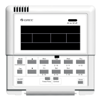
Floor Ceiling Air-Conditioning Unit
13
6 Control Flow Chart
See the following gure for the control ow chart of the smart zone controller.
All on/All off
(No press operation in 2.5 seconds)
Set the control command
(No press operation in 2.5 seconds)
Set the control command
(No press operation in 2.5 seconds)
Send out the control command
Send out the control command
Send out the control command
Single
Center
No press operation in 30 seconds
Centralized
Fig. 6.1 Control Flow Chart of the Smart Zone Controller
Note: As for rst energization, or change of process setting, or change of series port, it should
be adjusted again (see 5.3 for the method).
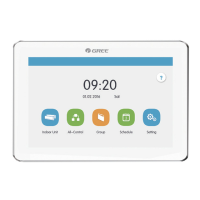
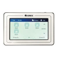
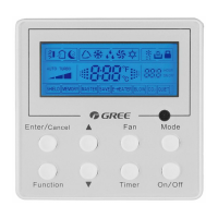
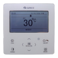
7 Viewing of the Running Status of the Indoor Unit and Control Mode
7.1 Viewing of the Running Status of the Indoor Unit
It can be seen generally on the LCD that the minimum code of the online indoor unit ashes,
with its running status, set temperature, and shield status etc. displayed. However, it can be
replaced by other expected indoor unit through pressing the corresponding indoor unit code button.
(If the expected indoor unit is ofine, then this operation is null and void with “no” displayed.).