Floor Ceiling Air-Conditioning Unit
7
5 Installation and Debugging
5.1 Installation
5.1.1 Installation Dimension Diagram
Fig.5.1 Installation Dimensions Diagram
5.1.2 Interfaces
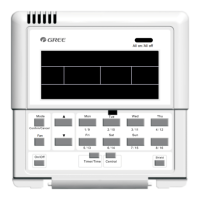
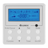
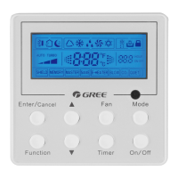
See Fig.5.2 for the interfaces of the display board and see Fig.4.3 for the interfaces of the
power supply module.
GND
+9.8V
CN1
COM1 COM2 COM3 COM4
CN2CN3CN4CN5
Fig.5.2 Interfaces of the Display Board Fig.5.3 Interfaces of the Power Supply Module Board