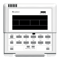
Floor Ceiling Air-Conditioning Unit
3
2.2 Communication Network
2.2.1 Units Connection
M
ax
.1
6
V
R
F
V
R
F
V
R
F
S
m
a
r
t
Z
o
n
e
C
o
n
tr
o
lle
r
D
u
c
t
T
y
p
e
/ F
r
e
e
M
a
t
c
h
W
ir
e
d
C
o
n
tr
o
lle
r
M
ax
.16
M
ax
.
16
M
ax
.16
P
o
rt
1
(V
R
F
)
P
o
rt
2
(
V
R
F
)
P
o
r
t
3
(V
R
F
)
P
o
r
t 4
(
D
u
c
t T
y
p
e
/ F
r
e
e
M
a
tc
h
)
M
ax
. 16
W
ir
e
d
C
o
n
t
r
o
lle
r
W
ir
e
d
C
o
n
t
r
o
lle
r
D
u
c
t
T
y
p
e
/ F
r
e
e
M
a
t
c
h
D
u
c
t
T
y
p
e
/ F
r
e
e
M
a
tc
h
Fig.2.1 Unit Connection Diagram
Note: the smart zone controller can connect with maximum three sets of multi VRF units and
multiple duct type units, however, the total of the indoor units of all four ports can not exceed 16.
2.2.2 Integration of the Smart Zone Controller and Long-distance Monitoring System/
Centralized Controller
Max.16
Centralized Controller
PC & Long-Distance Monitoring System
Max.16 Max.16
Max.16
Port 1 (VRF)
Port 2 (VRF)
Port 3 (VRF)
(Max.16 indoor units)
Smart Zone Controller
Communication Module
or
VRFV RFVRF
Duct Type / Free Match
Wired Controller
Max.16
Port 4 (Duct Type / Free Match)
Communication ModuleC ommunication Module
Wired ControllerWired Controller
Duct Type / Free Match Duct Type / Free Match
Fig.2.2 Connection of the Smart Zone Controller and the Long-distance Monitoring System/
Centralized Controller

 Loading...