Super Free Match
Service Manual
INSTALLATION
116
7 Electrical Wiring Work
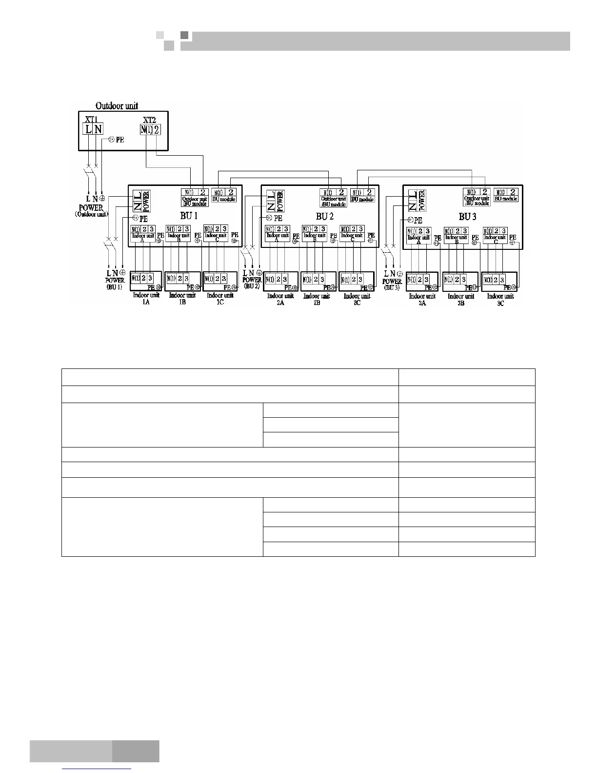
7.1 Wiring Connection
The “L”, “3” terminals are connected to the live wire, the “N”,”N(1)” terminals are connected to the neutral
wire and the”2” terminal is connected to the transmission line.
7.2 Requirements of Power Circuit and Cable
Phase and frequency 1Ph,50Hz
Voltage 220~240V
GWHD(42S)NK3CO
GWHD(48S)NK3CO
Recommended cable of outdoor unit
(Pieces × Sectional area)
GWHD(56S)NK3CO
3×6.0 mm
2
Recommended cable of BU module (Pieces × Sectional area) 3×0.75 mm
2
Transmission line (Pieces × Sectional area) 2×1.5 mm
2
Recommended cable of indoor unit (Pieces × Sectional area) 4×0.75mm
2
GWHD(42S)NK3CO 32A
GWHD(48S)NK3CO 40A
GWHD(56S)NK3CO 40A
Capacity of the air switch
BU module 10A
Note:
The total length of the transmission line between the outdoor unit and the furthest BU module is not more
than 55m. Otherwise, the system cannot work possibility.
The specifications of the power cable and transmission line listed in the table above are determined based
on the maximum power (maximum amps) of the unit.
The specifications of the power cable listed in the table above are applied to the conduit-guarded
multi-wire copper cable (like, YJV copper cable, consisting of PE insulated wires and a PVC cable jacket)
used at 40 and resistible to 90℃℃, and shall be at least those of ordinary polychloroprene sheathed cords
(code designation 60245 IEC 57). If the working condition changes, they should be modified according to
the related national standard.
The specifications of the air switch listed in the table above are applied to the breaker with the working
 Loading...