Super Free Match
Service Manual
INSTALLATION119
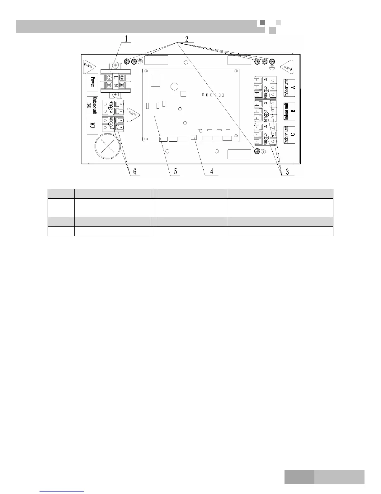
b) FXA3A-K and FXA3B-K
NO. 1 2 3
Name
Terminal black for BU
module power supply
Ground screw
Terminal black for indoor unit power
supply
NO. 4 5 6
Name DIP switch Printed circuit board Terminal black for transmission line
3) Let the power cable and transmission line go through the rubber ring. In order to protect the power cable
and transmission line from damaging by the hole, the rubber ring cannot fall from that, otherwise, it
may cause electrical shock or fire etc.
4) Connect the power cable of the BU module to the L, N terminals with the sign of Power and as well as
the ground screw.
5) Connect the transmission line of the BU module to the N(1), 2 terminals with the sign of Outdoor
unit/BU.
6) If the transmission line need to be connected to the other BU module, please connect the extra line to the
N(1), 2 terminals with the sign of BU.
7) Connect the power cable of the indoor unit to the N(1), 2 and 3 terminals with the sign of Indoor unit A
(B and C) and as well as the ground screw.
8) Fix the power cable and transmission line firmly by cable fixing clip.
9) Screw the electrical equipment plate.
Caution!
The transmission line and the power cable must be separated and separated with an interval of at least
2cm; otherwise it may be result in communication problem.
Confirm the each cable connected to the terminal screw is exactly and securely after finishing the electric
work.
Fix each ground wire separately with the ground screw.
When connecting indoor units, make sure to connect refrigerant pipes and power cables to the same
connection ports marked with matching signs (A, B and C).
If the connecting wire is connected to the terminal incorrectly, the unit will not work normally.
 Loading...