GMV DC Inverter VRF
52
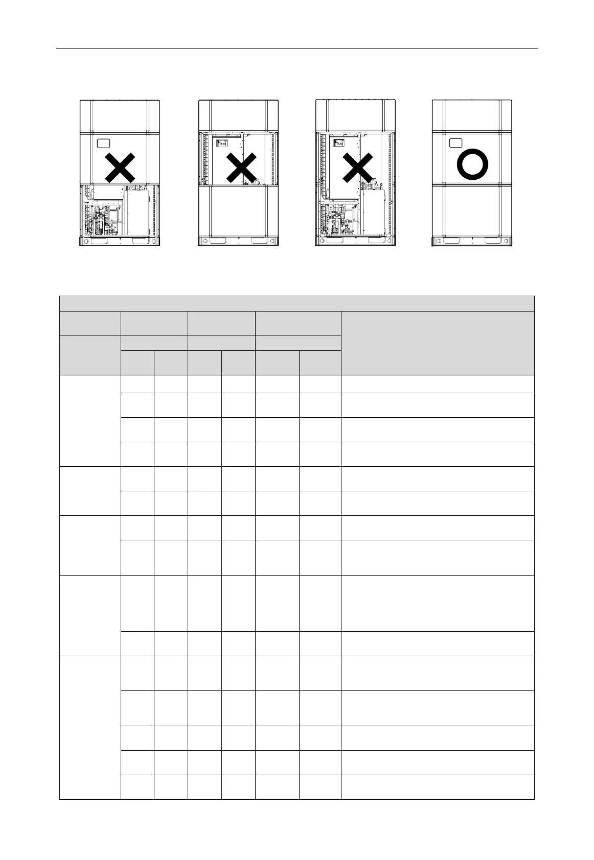
(3) When debugging, the front panel of the outdoor unit must be completely closed, otherwise it
will affect the accuracy of debugging (as shown in the Fig
.4.2.2
as below).
Fig.4.2.2
(4) Display instruction for each stage progress at the time of debugging:
Instruction for each stage progress at the time of debugging
—
Progress code Status code
Meaning
Progress
Code
Code
Code
01_set up
master unit
db ON 01 ON CC ON
The system hasn’t set master module. It
needs to reset it.
db ON 01 ON CF ON
The system has set more than 2 master
modules. It needs to reset it.
db ON 01 ON OC ON
Master module setting is succeeded. It will
automatically enter into the next step.
02_
a
llocate
addresses
db ON 02 ON Ad Flash
The system is conducting the address
assignment.
db ON 02 ON OC ON
Address assignment is succeeded. It will
automatically enter into the next step.
03_module
quantity
confirmation
db ON 03 ON 01~04 Flash
LED3 displays the module quantity. It needs to
manually confirm the module quantity.
db ON 03 ON OC ON
Once the system module quantity is
confirmed, it will automatically enter into the
04_indoor
unit quantity
confirmation
db ON 04 ON
quantity
of online
indoor
Flash
LED3 displays the quantity of online indoor
units.
db ON 04 ON OC ON
Indoor unit’s quantity inspection is finished.
Enter into the next step automatically.
05_detect
internal
communication
db ON 05 ON C2 ON
The system has detected “communication
malfunction between main control and inverter
db ON 05 ON C3 ON
The system has detected “communication
malfunction between main control and inverter
db ON 05 ON CH ON
Indoor/outdoor unit’s “rated capacity ratio is
too high”.
db ON 05 ON CL ON
Indoor/outdoor unit’s “rated capacity ratio is
too low”.
db ON 05 ON OC ON
System inspection is finished. Enter into the
next step automatically.
 Loading...
