Gree GMV6 DC Inverter VRF Units Service Manual
209
4.4.1 Mechanical Inspection
Step 1: Switch off the power of the ODU.
Step 2: Check whether the coil of the electronic expansion valve is firmly fixed on the electronic
expansion valve.
4.4.2 Electrical Inspection
Step 1: Power off the ODU and power on it. When the ODU is powered on again, the electronic
expansion valve should be reset. When the electronic expansion valve is reset, touch the valve with a
hand to check if the valve core rotates. In the second half of the resetting process, the valve core will click
and vibrate obviously; otherwise, the electronic expansion valve, coil or the main board needs to be
replaced.
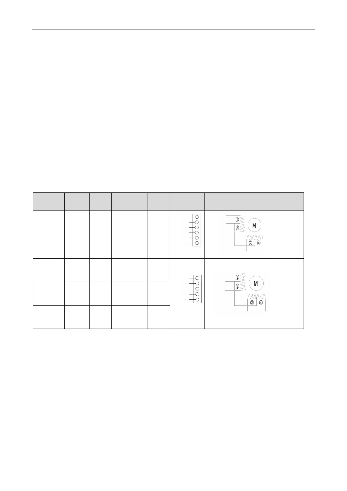
Step 2: Switch off the power of the ODU, disconnect the coil terminal of the electronic expansion
valve from the main board and use a multimeter to measure the resistance of each contact point of the
terminal. The normal range of the resistance is shown in the following table. If any value is beyond the
normal range, the coil is damaged and needs to be replaced.
Coil
Interface
No.
Color
Port
specifications
number
Terminal
layout
Diagram of internal coils
resistance
Heating
electronic
expansion
valve
CN19 White 6 cores 3000
White
Yellow
Orange
Blue
Red
Brown
Orange
Red
White
Yellow Brown Blue
100Ω±10Ω
electronic
expansion
CN20 Red 5 cores 480
Yellow
Gray
Orange
Red Black
46Ω±3Ω
electronic
expansion
CN17 Black 5 cores 480
electronic
expansion
CN18 White 5 cores 480
 Loading...
