Gree GMV6 DC Inverter VRF Units Service Manual
213
4.5.1 Mechanical Inspection
Step 1: Switch off the power of the ODU.
Step 2: Check whether the connector between the fan motor and fan drive board is firmly connected.
Step 3: Rotate the blades with a hand to check whether they can rotate smoothly and whether the
blades rub the baffle ring during rotation. If the blades are blocked during rotation, the motor needs to be
replaced; if the blades rub the baffle ring during rotation, check whether the blades and baffle ring deform
and needs to be replaced.
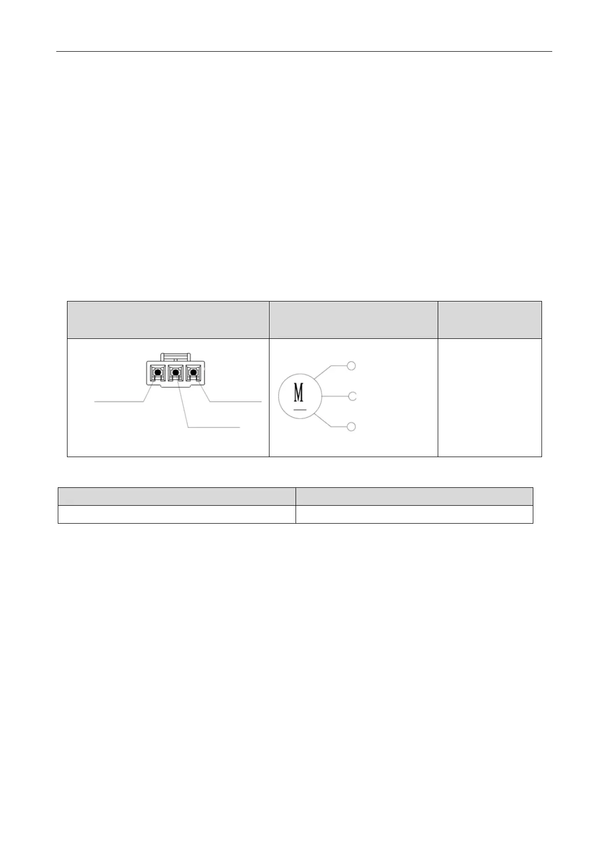
4.5.2 Electrical Inspection
Switch off the power of the ODU. Disconnect the connector between the fan motor and fan drive
board. Use a multimeter to measure the resistance of each contact point of the motor terminal. The normal
range of the resistance is shown in the following table. If any value is beyond the normal range, the motor
is damaged and needs to be replaced.
Terminal layout Diagram of internal coils
resistance between
3
.
W Blue
1.U Brown
2.V Black
U (
BN brown)
V (BK black)
W (BU blue)
10.2Ω±7%
4.6 Compressor
Specifications Description
Models: AA55PHDG-D1Y2, DA80PHDG-D1Y2 Compression refrigerant, recycling refrigerant.
 Loading...
