Gree GMV6 DC Inverter VRF Units Service Manual
3.2.3 Debugging Through the Main Board of Outdoor Unit
When conducting the debugging through the main board of outdoor unit, the main board has the
following debugging operation functions.
Step 1:
Cover all the front panels of the outdoor unit and open the debugging window of each basic
module.
Step 2:
When the outdoor unit is powered off, set one of the modules as the master module. For the
setting method, see “Master Module DIP Switch Code Setting (SA8_MASTER-S)”.
Step 3:
Under the power-on state of the outdoor unit, set the corresponding static pressure module
for the unit according to the design requirements of the outdoor static pressure of the project.
Step 4:
The module address is displayed as “01” is the master module. On the master module, press
and hold the SW3 confirmation button for 5 seconds or press the SW3 confirmation button for more than
10 seconds to enter the unit debugging function.
Step 5:
Wait. The unit automatically runs the steps 01 and 02 at this time.
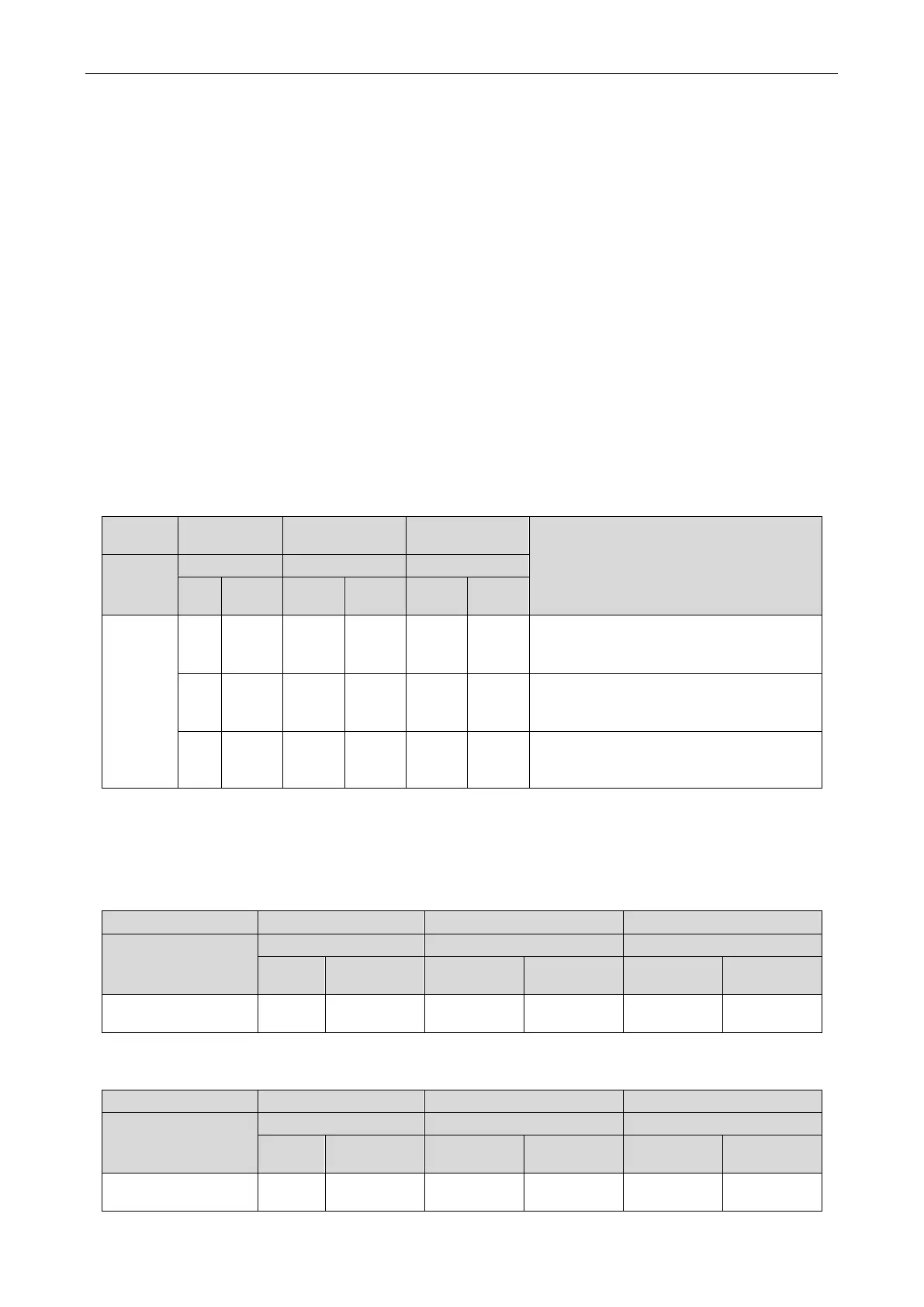
If the master module is set incorrectly in step 01, the following corresponding fault is displayed in
step 01:
—
Debugging
Progress code Status code
Meaning
Progress
Code
Display
Code
Display
Code
Display
01_ set up
master unit
db ON 01 ON CC ON
Mater module hasn’t been set in the
system. It needs to reset it.
db ON 01 ON CF ON
More than two master modules are set in
the system and it needs to reset it.
db ON 01 ON OC ON
Mater module of system has been set
successfully. Enter into the next step
According to the above fault phenomenon, reset the master module according to the setting method
of “Master Module DIP Switch Code Setting (SA8_MASTER-S)”, and re-enter into the debugging after
setting.
During the assignment process, all module digital tubes displays are as below:
—
Progress
LED1 LED2 LED3
Code
Display
Code
Display
Code
Display
02_allocate
db ON 02 ON Ad Flash
Step 6:
When the unit is running to step 03, it displays the number of modules connected to the
outdoor connection. At this time, the main board of each module is displayed as below:
—
Progress
Code
Display
Code
Display
Code
Display
03_ module quantity
db ON 03 ON
Module
Flash
 Loading...
