Gree GMV6 DC Inverter VRF Units Service Manual
If there is no refrigerant in the system or the amount of refrigerant does not meet the requirements
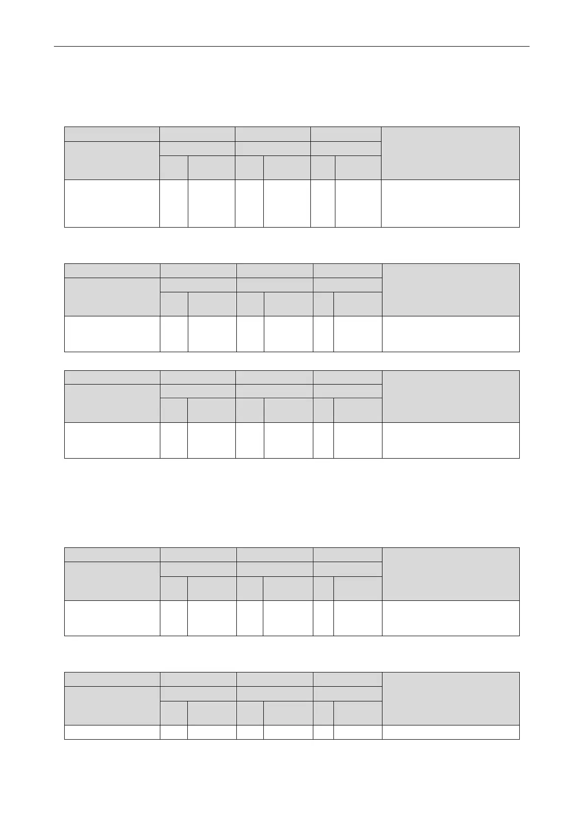
for starting operation, the unit will display U4 “Refrigerant-lacking protection”, as shown below. The unit
will enter into the next step. At this time, it is necessary to check whether there is a leak or charge some
refrigerant until the abnormality is eliminated.
—
Meaning
Progress
Code
Display
Code
Display
Code
Display
09_refrigerant
judgement before
startup
db ON 09 ON U4 ON
The refrigerant in the system is
insufficient. Please charge
refrigerant until the fault
Step 13:
Unit debugging step 10 is “status judgment of main pipeline before starting”.
If the main module displays as below, it indicates the unit is starting the operation for judgment.
—
Debugging code Progress code Status code
Meaning
Progress
Code
Display
Code
Display
Cod
Display
main pipeline before
db ON 10 ON ON ON Starting and operating.
If the unit has detected the abnormal status, the display is as below:
—
Meaning
Progress
Code
Display
Code
Display
Cod
Display
10_ status
main pipeline before
db ON 10 ON U6 ON Main pipeline is abnormal.
At this time, it is necessary to check whether the gas valve and the liquid valve are completely open
or whether the main pipeline is blocked. Once inspection is completed, you can return to the previous
step by pressing SW4 button to re-enter the judgment.
If inspection valve of the unit is normal, the display is as below. The unit will automatically enter into
the next step.
—
Meaning
Progress
Code
Display
Code
Display
Cod
Display
main pipeline before
db ON 10 ON OC ON
The main pipeline is turned on
normally.
Step 14:
Unit debugging step 11 is “reserved function”.
The main module display is as below. The unit automatically enters into the next step.
—
Meaning
Progress
Code
Display
Display
Cod
Display
—
Step 15:
Unit debugging step 12 is “reserved function”.
The master module display is as below. Then the unit automatically enters into the next step.
 Loading...
